• Skip to main content
  • Skip to primary sidebar

Making Easy Circuits

Learn and build electronic circuits

You are here: Home / New Circuits / TV Remote Control Tester Circuit

TV Remote Control Tester Circuit

Last Updated on January 10, 2018 by Admin Leave a Comment

Here is a straightforward TV remote control tester circuit that anyone can use to check TV and VCR remote handsets. The infrared sensor module generates a 5 volt logic pulse sequence in accordance with the digital signals of the specific remote device button pushed.

Other sorts of sensor devices can be purchased that are fitted with an inverted operation as confirmed in the second illustration which explains an alternative variety.

In the first circuit, the output is typically minimal without a transmission picked up and thus ends up being a positive running pulse sequence each time a signal is available.

The pulse process symbolizes the digital code of the selected button pushed in conjunction with supplier details. While the pulse sequence is transmitted, the 4.7uF capacitor is fully charged to roughly 3.1 volts along with the capacitor voltage minus a diode forward drop, transpires across the 470 ohm resistor producing a collector current from the BC557 of roughly 5 milliamps.

The collector current of the initial stage runs into the base of the output transistor BC547 which releases around 20 mA into the warning LED.

In case the pulse chain concludes, the capacitor eventually discharges by means of the base of the first stage transistor leaving the LED light to continue running for a approximately 1 second.

The LED is going to work over a large voltage spectrum, so you are able to implement other sorts of lamps from just about any application.
The TV remote control tester circuit is usually powered from a compact 9-12 volt DC, 200 mA or bigger wall transformer. It could possibly also have to have a supplementary 1000 uF filter capacitor around the output in case the wall transformer does not necessitate an integrated cap.

Specifically using a 9 volt power supply, the green LEDs could be swapped over by a white or red LED as well as the output transistors could very well be changed with little signal transistors. The combined current dissipate will probably be approximately 20 mA with the LED illuminated, not to mention 15 mA extra while the LED is off.
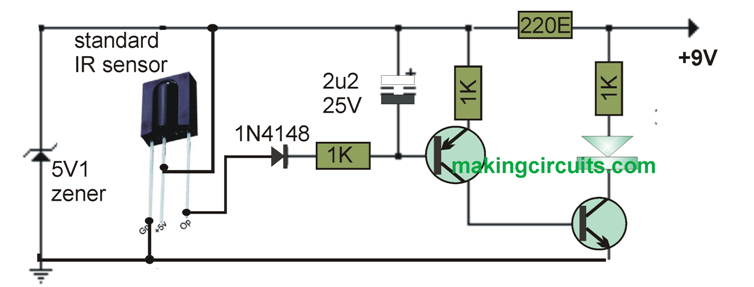
 

TV remote control tester circuit

Transistors can be BC547 for the NPN, and BC557 for the PNP
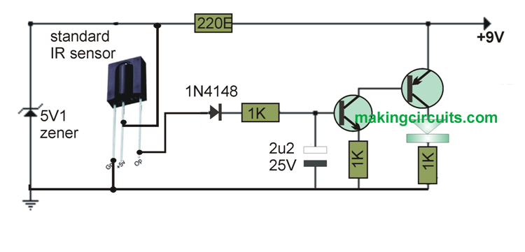
tester1


You'll also like:

  • 1.  How to Build a Wireless Home theater Circuit using Bluetooth Headset
  • 2.  Discotheque Music Level Indicator Circuit
  • 3.  Motor Dry Run Protection Circuit using IC4049
  • 4.  Easy FET Circuits you can Build and Use
  • 5.  Precision Temperature Alarm Circuits using Op Amps
  • 6.  Burp Sound Simulator Circuit

About Admin

Hey friends, Thanks a bunch for stopping by this site! I am an engineer with a Bachelor of Engineering in Electronics and Telecommunication. One of my passions is gathering information from all sorts of electronics books and tutorials. I then take that information and compile it into a language that is super easy to understand. My goal is to make those complex electronics circuit concepts and technical terms much more accessible for all the new and budding electronics engineers out there. I can also design customized circuit diagrams as required by the users.
If you have any questions related to this field, please do not hesitate to drop a comment! I am always here and ready to help you out with any queries you might have. I cannot wait to hear from you!

Reader Interactions

Leave a Reply Cancel reply

Your email address will not be published. Required fields are marked *

Primary Sidebar

Categories

  • 3 Phase (4)
  • 8051 Microcontroller (1)
  • Arduino (11)
  • Audio and Amplifier (102)
  • Automation (8)
  • Battery Chargers (64)
  • Bicycle Projects (4)
  • Car and Motorcycle Projects (39)
  • Datasheets (10)
  • DIY Projects (5)
  • Electrical (15)
  • Free Energy (6)
  • Games Projects (2)
  • High Voltage (14)
  • Hobby Projects (30)
  • Household Circuits (2)
  • IC 555 Circuits (4)
  • Ignition Circuits (2)
  • Indicators (50)
  • Infrared (6)
  • Inverter Circuits (29)
  • Lights and Lamps (97)
  • Medical (8)
  • Meter and Tester Circuits (38)
  • Motor Driver (17)
  • New Circuits (56)
  • Oscillators (30)
  • Pets and Pests (5)
  • Power supply (81)
  • Protection Circuits (25)
  • PWM (8)
  • Remote Control (20)
  • Security and Alarm Circuit (48)
  • Sensors and Detectors (66)
  • Signal Processor (23)
  • Solar Controller Circuits (61)
  • SSR (3)
  • Temperature Controller (20)
  • Timer (25)
  • Transformerless (7)
  • Transmitters (12)
  • Tutorials (45)
  • UPS (2)
  • Voltage Regulators (57)
  • Water Sensor and Controller (29)
  • Home
  • Privacy Policy
  • Contact
  • Disclaimer
  • Copyright

© 2025 · Making Easy Circuits