• Skip to main content
  • Skip to primary sidebar

Making Easy Circuits

Learn and build electronic circuits

You are here: Home / Electrical / Types of Resistors

Types of Resistors

Last Updated on May 16, 2019 by Admin Leave a Comment

A resistor is a passive electronic component designed to provide resistance to current in a circuit. There are various forms of resistors. These resistors differ with their structure, power rating, and tolerance levels to numerous factors (for example heat and light). The various types of resistors are as given below:

  • Carbon Composition Resistor
  • Thermistor
  • Wire Wound Resistor
  • Metal Film Resistor
  • Carbon Film Resistor
  • Variable Resistor
  • Varistor
  • Light Dependent Resistor


Carbon Composition Resistor

A carbon composition resistor (also referred to as a carbon resistor) is the most typically used resistor in electronics.

These types of resistors are usually cheap and easy to produce. Carbon resistors mostly are manufactured from carbon clay arrangement protected through a plastic material enclosure. The terminals of the resistor is built out of tinned copper.

Carbon Composition Resistor

The main features of these resistors are that they're readily accessible from your nearby market and these are extremely sturdy as well. These resistors can be purchased in a many different values.

You will find it as low as 1 Ω value while also with values of up to 20 Mega Ω. Yet the major downside is they are extremely vulnerable to temperature changes.

The tolerance range of these resistors lie around at ± 5 to ± 20 %. These have an inclination of developing RF noise caused by the flow of electrical current across the carbon constituent inside it.

For applications where affordability is the central criteria for creating a circuit rather than high efficiency, these resistors are typically employed.

Carbon resistors come with unique shaded bands printed over their cylindrical body. These color bands are actually color codes for exhibiting or calculating their values and tolerance range.


Thermistor

The phrase thermistor relates to a thermal based resistor. Its resistance changes with respect to temperature changes.

thermistor internal construction

The majority of the thermistors possess a negative temperature coefficient meaning its resistance drops when temperature around it increases.

They are typically manufactured from semiconductor elements. A resistance up to a some mega ohms is normally available for thermistors.

They are utilized for sensing minute variations in temperature.

When it detects a change in ambient temperature, no matter how small, we find a rather substantial enhancement on the value of its resistance.


Wire Wound Resistor

In wire wound resistor a wire made from manganin or constantan is wound over a cylinderical material having high insulation property.

eNkDm

However the main drawback of these types of resistors is the generation of inductance, due to its round coil like shape. Because of this at high frequencies this inductance get significantly large giving rise to other complex issues in the circuit.

The issue is normally corrected by winding opposite turns across the two halves of the unit,, which results in cancelling of the inductance and minimizing its effects. This type of upgraded wire wound resistors become ideal in critical high frequency circuits, but can be costlier for normal circuits.

The temperature coefficient of resistance of manganin and constantan is practically zero.

Therefore, changes in resistance due to temperature variations is found to be minimal for these resistances.

The wire winding is protected with an strong insulation layer that include hardened enamel. This specific insulation is highly resilient to heat and has the property of negating the influence ambient temperature changes.

Various measurements and ratings of wire wound resistor can be simply attained through the use of distinct measures and diameters of the wire Turns.

These types of resistors can be obtained with a wide range of values. The resistance range may vary from 1 Ω to 1 MΩ.

Standard tolerance limitation of these resistors ranges from 0.01 % to 1 %.

They may be applied for high power applications ranging from 10 watt to 200 W power ratings.

The price of these resistors is significantly higher compared to carbon resistors.

Commonly wire wound resistor is needed in areas where carbon resistor would burn due to low power limitations.

Carbon Film Resistors or CFR

Metal film resistors are manufactured by applying a fine layer of a conductive material like carbon or any similar metal over an insulating base.

carbon film resistors

The value is established by either trimming the thickness layer or by scraping helical channels with the desired width along the length of the carbon layer.

Metal Film Resistors

In this type of resistors you will find metal caps plugged at the ends of the resistors which are connected to a conductive film with helical grooves.
The end metal caps are fused with the leads of the resistors or the wire terminals.

mfr

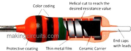
These are also called metal film resistors or MFR, and could be produced with values as high as 10K MΩ. It's size is much tinier compared to wire wound types.

Their internal configuration is such that no inductance can developed in them and therefore these are pretty accurate with their tolerance level, which is around +/- 1%.

MFRs are normally applied in high precision electronic circuits due to their high tolerance feature.

Variable Resistor

As the name suggests in a variable type of resistors the resistor is adjustable. A potentiometer is an example of a variable resistor.

images

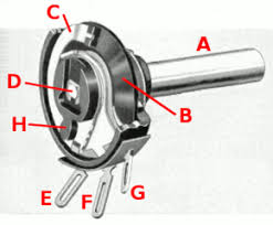
Image of potentiometer with body disected, showing parts: (A) shaft, (B) stationary carbon composition resistance element, (C) phosphor bronze wiper, (D) shaft attached to wiper, (E, G) terminals connected to ends of resistance element, (F) terminal connected to wiper.

It basically is made up of a central shaft which can be rotated through a wiping movement over a semi-circular flat base contact.

This semi-circular base contact is layered with resistive material, which gives a varying resistance value across the shaft when its moved on this contact.

In its bigger form a variable resistor is named as rheostat. In this equipment a linear sliding contact slides over a resistive elemnt linearly for getting a varying resistance across its termianls.

Non Linear Resistor or Varistor

These form of resistors are also called varistors and are popular for their non-linear V/I characteristic curve.

varistor or mov

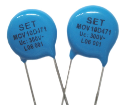
Due to this attribute the device develops a resistance which is non uniform and apparently does not obey Ohm's law.
These are made up of materials like silicon carbides, zinc oxide.

Basically there are 3 types of varistors in the market:
Silicon carbide disc type varistor
Silicon carbide rod type varistor
Zinc oxide type varistor

Light Dependent Resistor

A light dependent resistors or an LDR has the property of varying its resistance value when light or any of form of illumination is applied on it. Its resistance value drops as the intensity of light on it increases and vice versa.

Light Dependent Resistor

These are built using the material cadmium sulfide with a smaller quantity of electrons while it's in darkness. This causes a relatively high resistance across its terminals.

However when light falls on an LDR surface, the material reacts with light photons and start ejecting more number of electrons which in turn causes higher conduction across the LDR terminals, subsequently causing a significant drop in its resistance value..

You'll also like:

  • 1.  Voltage to Current Converter
  • 2.  How to Design IC 555 Astable Circuit
  • 3.  Simple Transistor Latching Circuit Explained
  • 4.  How to Build a Calculating Flyback Diode/Resistor for High Current Inductors
  • 5.  Basic Electronic Formulas for Devices
  • 6.  How to Calculate Capacitor Series Parallel Connections

About Admin

Hey friends, Thanks a bunch for stopping by this site! I am an engineer with a Bachelor of Engineering in Electronics and Telecommunication. One of my passions is gathering information from all sorts of electronics books and tutorials. I then take that information and compile it into a language that is super easy to understand. My goal is to make those complex electronics circuit concepts and technical terms much more accessible for all the new and budding electronics engineers out there. I can also design customized circuit diagrams as required by the users.
If you have any questions related to this field, please do not hesitate to drop a comment! I am always here and ready to help you out with any queries you might have. I cannot wait to hear from you!

Reader Interactions

Leave a Reply Cancel reply

Your email address will not be published. Required fields are marked *

Types of Resistors and their Working Differences Explored

Last Updated on February 23, 2016 by Admin Leave a Comment

The industry of electronic circuits uses resistors of various different types available in the market. The properties of these resistors vary and are different for each type being ruled by their manufacturing and construction process.

By: S. Prakash

Over a time period, the resistors of various types which were and are being used in the production of electronics have undergone continuous change.

The resistors which were used previously consisted of lead as their component along with being very large in size when compared to the resistors of the present day which resulted in low performance level of the former.

The current day resistors are comparatively smaller in size along with performing at a high level.

Resistors of variable and fixed types

The most major and basic category in which a resistor can be differentiated is on their nature of being either of variable or fixed type. The applications for which these resistors of different types are used differ respectively.

Fixed Resistors: The resistor which is used most widely in the industry is the fixed resistors. The electronic circuits use the fixed resistors for correcting and setting the right and appropriate conditions within their circuits.

The determination of the values of the resistors is carried out in the circuit’s design phase. These values are not required to be adjusted or changed in any manner with respect to the circuit.

The decision as to which resistor type needs to be used is dependent on the various circumstances in which they are to be used. These resistor types have been described in further detail in the subsequent sections.

Variable Resistors: The variable resistors consist of two elements, namely a fixed resistor element. The main element of the resistor is tapped onto by the slider present in the resistor.

potentiometer variable resistor

Thus, this provides the resistor’s components with three connections. Out of these three connections, the fixed element is fixed to the two connections while the slider is the third connection.

Thus, this enables the components to act as an agent of the variable potential divider.

This also required that they use the three connections altogether. The variable resistance can be provided to the resistor by connecting the one end of the resistor with the slider.

Potentiometers, presets and rheostats are some of the common examples of variables resistors

Resistors of Fixed Types

The various different fixed resistor types are as follows:

Carbon composition: The carbon composition resistors were very common previously but the currently their usage has decreased considerably.


carbon composition resistors

The carbon resistors are manufactured by mixing the granules of the carbon with an element which acts as a binder and this mixture in turn is made in the shape of small rods.

The carbon resistors had a disadvantage in terms of suffering from a very high negative temperature coefficient.

This is due to their comparatively large size when viewed from the current day standards.

The carbon composition resistors also suffered another downfall wherein due to aging of the resistor with time or an exposure to excessive heat, the carbon composition resistor goes through irreversible changes which are erratic and large.

Additionally, a large amount of noise is generated in the carbon composition resistor when the current flows through it because of the carbon’s granular nature and its association with the binder.

Carbon Film (CFR 5%): The carbon film resistor is manufactured by the induction of the process of a hydrocarbon’s cracking into a former made up of ceramic.


carbon film resistor CFR 5%

The resistance of the film which is deposited as a result of the above process is set by making a cut into the film in the shape of helix. This has resulted in very high inductance in the carbon film resistors and thus most of the RF applications cannot use it much.

A -900 ppm/ºC to -100 ppm/ºC of temperature coefficient is exhibited by the carbon film resistors. A ceramic tube or a conformal epoxy coating is used to protect the carbon film.

Metal Oxide Film (MFR 1%): The metal oxide film resistor has come to become the resistor which is used in the current day industry at a wide scale along with another resistor type of the metal film type.


metal film resistor MFR 1%

The metal oxide film resistor type uses a film of metal oxide instead of a carbon film to be deposited on the ceramic rod.

The deposition of the metal oxide which can be found on the ceramic rod can include tin oxide. There are two ways in which the component’s resistance is adjusted.

Firstly, at the initial stages of the manufacturing process, the deposited layer’s thickness is controlled. Thereafter the adjustment is done in more accurate way by cutting a grove in the shape of helical form in the film.

Again, as in the previous case, the conformal epoxy coating is heavily coated on the film to protect it.

The ±15 ppm/ºK of temperature coefficient has been observed in the metal oxide film resistor which results in a very high and superior function of this resistor when compared to any other resistor which is carbon based.

Additionally, the tolerance levels to which these resistors are supplied are very close including the standard tolerance levels of ±2%, ±1%, and ±5% being available.

Also, when compared with the resistors which are carbon based, there is very low exhibition of noise in these resistors.

Metal Film: There is a great similarity which can be observed between the metal oxide film resistor and the metal film resistors in terms of their performance and appearance.

A metal film is used by this resistor in place of the metal oxide film which is used in the metal oxide film resistor. The metal film which is used in the resistor can include nickel alloy.

Wire Wound: The applications which require very high power in general use this type of resistor. A wire is wounded around a former in order to manufacture this type of resistors.


wire wound resistor 100 ohm 10 watt

The resistance of these wires is higher than that of the normal resistance. The varieties of these resistors which are expensive consist of the wire which is wound on a former made up of ceramic along with a cover of the silicone or citreous enamel over it.

The temperature coefficient of these resistors is very low along with a reliability of very high level being exhibited by these resistors when exposed to high power which enables it to operate at high performance level.

But these properties are also dominated by various other factors such as type of the wire being used, type of former being used, and more.

Thin Film: The majority of the resistors which are of surface mount types use the technology of the thin film. The resistors based on this technology are used widely in the current day industry where the number goes up to billions here.

Non-Leaded and Leaded types of Resistors

The manner in which the components or the resistors are connected acts as an important determinant of the differentiation of the components and the resistors.

The manner in which the components were connected previously has changed over the time majorly due to the use of the techniques of mass production and the circuit boards being used at a widespread level.

This is especially true for the components which the mass production process incorporates.

On the basis of the method of connection, the two major categories of the resistors are as follows:

Leaded Resistors: Since the times when the electronic components had first come into use, the leaded resistors had also come into use since those times.

The lead which came from the element of the resistor were required wherein the components were required to be connected in various different forms to the terminal posts.

Their usage has not stopped till date and only technique has changed wherein in the current practices where there is more use of the printed circuit boards, the holes present in the boards are used to insert the lead and then the reverse side is used to solder it where one can find the tracks.

Surface Mount Resistors: The since the time when the technology of the surface mount have been introduced, there has been a significant increase in the surface mount resistors.

Surface Mount Resistors

The technology which is used to manufacture the surface mount resistor is the thin film technology. Through this technology, the resistor can obtain the values in full range.

You'll also like:

  • 1.  2N3906 Datasheet [40V, 200 mA PNP Transistor]
  • 2.  TL431 Circuits and Datasheet
  • 3.  List of all Commonly used Transistors (BJT)
  • 4.  IC 4093 NAND Gates, Pinouts Explained with Diagrams
  • 5.  Understanding IC 4043 Pinouts, Datasheet
  • 6.  Solid State Relay (SSR) Circuit using Triac and OptoCoupler

About Admin

Hey friends, Thanks a bunch for stopping by this site! I am an engineer with a Bachelor of Engineering in Electronics and Telecommunication. One of my passions is gathering information from all sorts of electronics books and tutorials. I then take that information and compile it into a language that is super easy to understand. My goal is to make those complex electronics circuit concepts and technical terms much more accessible for all the new and budding electronics engineers out there. I can also design customized circuit diagrams as required by the users.
If you have any questions related to this field, please do not hesitate to drop a comment! I am always here and ready to help you out with any queries you might have. I cannot wait to hear from you!

Reader Interactions

Leave a Reply Cancel reply

Your email address will not be published. Required fields are marked *

Primary Sidebar

Categories

  • 3 Phase (4)
  • 8051 Microcontroller (1)
  • Arduino (11)
  • Audio and Amplifier (102)
  • Automation (8)
  • Battery Chargers (64)
  • Bicycle Projects (4)
  • Car and Motorcycle Projects (39)
  • Datasheets (10)
  • DIY Projects (5)
  • Electrical (15)
  • Free Energy (6)
  • Games Projects (2)
  • High Voltage (14)
  • Hobby Projects (30)
  • Household Circuits (2)
  • IC 555 Circuits (5)
  • Ignition Circuits (2)
  • Indicators (50)
  • Infrared (6)
  • Inverter Circuits (29)
  • Lights and Lamps (97)
  • Medical (8)
  • Meter and Tester Circuits (38)
  • Motor Driver (17)
  • New Circuits (56)
  • Oscillators (30)
  • Pets and Pests (5)
  • Power supply (80)
  • Protection Circuits (25)
  • PWM (9)
  • Remote Control (20)
  • Security and Alarm Circuit (48)
  • Sensors and Detectors (66)
  • Signal Processor (23)
  • Solar Controller Circuits (62)
  • SSR (3)
  • Temperature Controller (20)
  • Timer (25)
  • Transformerless (7)
  • Transmitters (12)
  • Tutorials (45)
  • UPS (2)
  • Voltage Regulators (57)
  • Water Sensor and Controller (29)
  • Home
  • Privacy Policy
  • Contact
  • Disclaimer
  • Copyright

© 2025 · Making Easy Circuits