In this post we discuss several different types of electronic touch switch circuit, which can be used to toggle an electrical load simply by touching a piece of metal connected at the input of the circuit.
I an electronic touch switch circuit we have an input metal pad, and an attached electronic circuit which sensed the touch contact on the touch pad. When a finger contact is sensed, the circuit converts that contact into an electrical pulse which is subsequently used to operate an relay ON/OFF. This relay finally is used to switch ON or switch OFF an external electrical load.
Drawback of Mechanical Switches
The primary drawbacks of the mechanical push-button switch are that it is unstable, seems to be a little pricey, and is only accessible in the configurations which the manufacturers choose to make.
These switches are also 'noisy,' causing contact-bounce spikes that can wreak trouble with fast switching electronic circuits.
Basic Electronic Debouncer
The 'debouncer' circuit design of Fig 1 shown below can be used to solve the issue described above.

As just a basic Schmitt trigger, only quarter of an IC 4093B CMOS quad 2 input NAND Schmitt is employed. C1 speedily charges to entire supply volts as soon as PB1 is closed, and the Schmitt output flips high: Once PB1 is released, C1 progressively discharges through R1 until the Schmitt output returns to zero.
As a result, switch contact bounce has no effect on the circuit, and the Schmitt output provides a smooth on/off signal.
Basic Electronic Toggle Switch
A toggling (alternating on - off) function may be obtained from a basic push-button switch, as shown in Fig. 2. R1 -C1 debounces the switch signal, that is then utilized to pulse one half of the 4027B dual JK flip-flop, that splits the clock signal in half.

As a result, the output of the IC 4027B turns high on the first press, and turns low on the second, then high on the next, and so on. Each IC 40278 IC may be used to create two such toggle switches.
Solid-state switches offer the following advantages: they are dependable (no bothersome moving parts), these might be less costly compared to their electro-mechanical equivalents, and these can be manufactured in nearly whatever shape or form that the manufacturer or constructor desires.
Electronic Touch Switch Categories
Touch switch circuits are divided into three categories (excluding 'weird' circuits like thermo-switches, etc.). The'resistive' varieties are the most basic and unattractive, relying on the 'touched' or 'untouched' resistance variations that happens between two adjoining touch contacts to provide switching operations.
Resistive Touch Switch
A simple resistive touch switch circuit is shown in Figure 3. R1 normally keeps the Schmitt input high and the output low while the contacts are not being touched.

The skin resistance (lower than 3Meg) created by bridging the two contacts with a finger drags the Schmitt input low and forces the output high. The circuit is 'debounced' using C1. The circuit may be adapted to offer 'toggle' action or flip flop action, as shown in Fig. 4 below.

Moisture or pollution bridging across the contacts might deactivate the resistive touch switch, which is a major drawback. This may also be rendered inoperable by people with wet fingertips or resistant to operations by those with extremely dry fingertips.
Hum Sensing Switch
A second form of 'hum sensing' touch switch provides a significant increase in dependability. The human body works as a form of antenna which is connected to the utility grid and emits a high-impedance main power signal, allowing this type of circuit to work.
This design of circuit can be seen in the Fig. 5 below.

The humming pick-up signal is supplied to the input of the first Schmitt stage through limiting resistor R2 whenever the input contact is tapped, resulting in a full-amplitude square wave at the Schmitt output.
The D1 -R3 -R4 -C1 circuitry converts this square wave to DC and debounces it, driving the second Schmitt high's ultimate output. Just after input touch is withdrawn, the Schmitt output drops to zero after 60 milliseconds.
D2 and C2 avoid undesirable feedback from the 4027 IC to the Schmitt in Fig. 6 below, which demonstrates how the aforesaid circuit may be updated to produce toggling operation.

Capacitive Touch/Proximity Switches
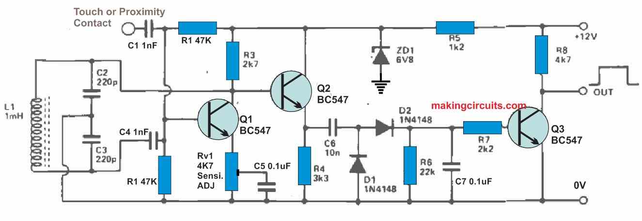
The experimental circuit of a touch/proximity switch based on the oscillator damping concept is shown in Fig. 7 below.

The oscillator is a Colpitts, which operates at a frequency of around 300 kHz. As soon as the contact remains undisturbed, RV1 is skillfully adjusted until the oscillation is slightly sustained.
The rectified output of the oscillator pushes Q3 to saturation and keeps the circuit's output at low logic in this situation. The moment the contact is pressed, capacitive loading disables the oscillator, forcing Q3 to shut off causing the output to flip high.
The output has a long rise and fall period, however a Schmitt circuit may be used to ramp things up if needed.
In the Fig. 8 circuit, as shown above, the zero volts line must (preferably) be connected to the ground line.
The touch contact should be constructed of electrical conductor, although this can be of any size or shape. In majority of the circumstances, the 'contact' side could be coated with an insulating substance without compromising the circuit's effectiveness.
Real contact administration is required for pin-head sized contacts, however 'contacts' having a touch area of a square metre or more can be proximity controlled at ranges up to 20 - 40 cms.
Capacitor Divider Touch Switch
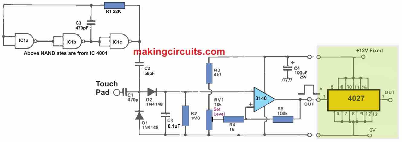
Lastly, Fig. 8 below depicts the circuit of a capacitive-divider touch switch. IC1 is configured as a ring-of-three oscillator with a frequency of a several hundred kHz in this example.

C2 and the spurious capacitance around D1 and the touch contact produce a capacitive voltage divider with the oscillator output.
The output signal of the potential divider is rectified by D1 - D2 - C3 - R2 and sent to the IC 3140 regenerative voltage comparator, which is modified (via RV 1) such that its output is simply switched to the low state when the input contact is left open.
As soon as the contact is tapped, the capacitive loading raises the bottom half of the potential divider's effective capacitance, lowering the divider's output voltage and forcing the IC 3140 output to flip high.
An add-on portion is shown at the exreme right using IC 4027 may be utilized to convert the circuit to toggling functioning. The zero volt line of the above design must be grounded, just like it was implemented in the Fig. 7 circuit.
The touching contacts may be whatever shape or size you like.
THats a great article
thank you….
Capacitive touch/proximity switches
The experimental circuit of a touch/proximity switch based on the oscillator damping concept is shown in Fig. 7 below.
I have a problem from C6 10 nf nothing works anymore and the resistor R8 has burned out.
The Colpitts oscillator, with a frequency of 300 kHz, works very well, question what can the error come from?
You are saying R8 burned out, but how can R8 burn since it is a 4k7 resistor, even if Q3 emitter/collector are shorted still R8 cannot burn…something might be wrong in your circuit.
Hello it works perfectly! I can even connect two relays, one relay on touch and one on proximity.
Thank you all, the circuit diagram is just great
Thank you, glad to know you could build the circuit successfully.
Updates essential
thanks.