• Skip to main content
  • Skip to primary sidebar

Making Easy Circuits

Learn and build electronic circuits

You are here: Home / Datasheets / Understanding IC 4043 Pinouts, Datasheet

Understanding IC 4043 Pinouts, Datasheet

Last Updated on February 17, 2018 by Admin Leave a Comment

The article talks about the pinout activity as well as other crucial specs of the IC 4043. Let's find out about the total datasheet of this quite interesting chip.

Pinout Datasheet of IC 4043

Theoretically the IC 4043 is a quad set/reset (R/S) latch with 3 logic state output.

To become more accurate this chip has 4 sets of inputs (which means 8 input pinouts) and 4 related single outputs.

The 4 sets of inputs are comprised of 4 pairs of set/reset inputs.

For each and every set/reset we certainly have one corresponding output.

Each one of these set reset inputs react to high logic signals, producing a bistable impact at their related output pinouts.

Bistable describes flip flop action, quite simply a high pulse to the "set" input makes the corresponding output high from its original low state, and a high to the reset input reverts the above state from high back to low state.

Consequently essentially to create a corresponding outputs high, we have to employ a high on their "set" inputs and to make the outputs low once again we simply require to use an additional high to their reset inputs.

The working of the input and output pinouts are as easy as that.

Furthermore, the IC has one more fascinating input pinout OE which happens to be a common output enable pinout.

For allowing the above described set/reset actions in the IC, this OE input ought to be associated with logic high or simply just with Vdd (supply votage).

In the above circumstance the output is permitted with the stipulated flip flop functioning.

If the OE input is linked with ground, the output freezes and generates a high impedance reply, that is neither demonstrates a low output nor a high, rather locks input a unresponsive blocked state, therefore the name 3 logic state output.

Thus the OE input may be used to turn off the IC working if essential to a specific application.

The IC is most effective with supply voltages from 5 to 15V.

Understanding IC 4043 Pinouts, Datasheet

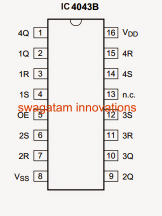
Let's sum up the input output pinout benefits and requirements of the IC 4043 with the following information:

1Q to 4Q (Pins: 2, 9, 10, 1) 3-state buffered latch output
1R to 4R (Pins: 3, 7, 11, 15) reset input (active HIGH)
1S to 4S (Pins: 4, 6, 12, 14) set input (active HIGH)
OE (Pin:5) common output enable input
VSS (Pin: 8) ground supply voltage
N.C. (Pin: 13) not connected
VDD (Pin: 16) supply voltage

You'll also like:

  • 1.  2N3904 Datasheet [40V 200mA NPN Transistor]
  • 2.  LF351 Op-Amp IC : Datasheet, Pin Details, Application Circuits
  • 3.  List of all Commonly used Transistors (BJT)
  • 4.  Solid State Relay (SSR) Circuit using Triac and OptoCoupler
  • 5.  TL431 Circuits and Datasheet
  • 6.  2N3906 Datasheet [40V, 200 mA PNP Transistor]

About Admin

Hey friends, Thanks a bunch for stopping by this site! I am an engineer with a Bachelor of Engineering in Electronics and Telecommunication. One of my passions is gathering information from all sorts of electronics books and tutorials. I then take that information and compile it into a language that is super easy to understand. My goal is to make those complex electronics circuit concepts and technical terms much more accessible for all the new and budding electronics engineers out there. I can also design customized circuit diagrams as required by the users.
If you have any questions related to this field, please do not hesitate to drop a comment! I am always here and ready to help you out with any queries you might have. I cannot wait to hear from you!

Reader Interactions

Leave a Reply Cancel reply

Your email address will not be published. Required fields are marked *

Primary Sidebar

Categories

  • 3 Phase (4)
  • 8051 Microcontroller (1)
  • Arduino (11)
  • Audio and Amplifier (102)
  • Automation (8)
  • Battery Chargers (64)
  • Bicycle Projects (4)
  • Car and Motorcycle Projects (39)
  • Datasheets (10)
  • DIY Projects (5)
  • Electrical (15)
  • Free Energy (6)
  • Games Projects (2)
  • High Voltage (14)
  • Hobby Projects (30)
  • Household Circuits (2)
  • IC 555 Circuits (5)
  • Ignition Circuits (2)
  • Indicators (50)
  • Infrared (6)
  • Inverter Circuits (29)
  • Lights and Lamps (97)
  • Medical (8)
  • Meter and Tester Circuits (38)
  • Motor Driver (17)
  • New Circuits (56)
  • Oscillators (30)
  • Pets and Pests (5)
  • Power supply (80)
  • Protection Circuits (25)
  • PWM (9)
  • Remote Control (20)
  • Security and Alarm Circuit (48)
  • Sensors and Detectors (66)
  • Signal Processor (23)
  • Solar Controller Circuits (62)
  • SSR (3)
  • Temperature Controller (20)
  • Timer (25)
  • Transformerless (7)
  • Transmitters (12)
  • Tutorials (45)
  • UPS (2)
  • Voltage Regulators (57)
  • Water Sensor and Controller (29)
  • Home
  • Privacy Policy
  • Contact
  • Disclaimer
  • Copyright

© 2025 · Making Easy Circuits