This article here is about one very simple, but super flexible 100-amp variable voltage power supply circuit. We are just using only some BJTs, all connected together in parallel and they are in common collector mode. That is it. This whole idea, we got it from Mr. Valery.
Technical Specifications
Dear Admin
I am coming to you because I really, really need your help. That is why I am here. Now I have seen many, many simple variable power supply circuits here and there on different blogs, scattered everywhere. But the problem is I actually do not know much about electronics at all. That is the main thing.
But even then I strongly believe that if I can get a proper list of parts and a really good circuit diagram, then maybe I can build this thing myself. That is what I am hoping for.
Now what I seriously want to make is just a simple adjustable power supply. We will give it 220V or 240V AC at the input and then the output voltage should be adjustable from around 1.5V to 15V. But not only that, the current should also be adjustable, and it has to go up to around 100A maximum.
Now why do I need this thing? That is because I have just started doing zinc electroplating as a hobby. My hands sweat a lot, too much actually, so I need some way to protect my tools. So I got all my chemicals from a supplier, and that guy told me that for the size of my zinc plating bath I need this exact kind of power supply. That is what he said.
Right now I am trying to do electroplating with a small Ryobi battery charger which is rated at 6V and 8A. But the problem is, it only works for some time, and then it gets too hot and shuts down. Then I have to wait for it to cool down again before I can use it. This is really, really frustrating for me.
So if you can help me in any way with this then I will be extremely extremely thankful to you.
Thank you so much.
Valery
The Circuit Design
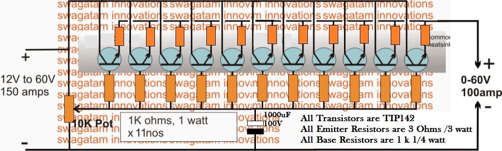
Here we are talking about one very simple circuit design for this 100-amp variable voltage power supply. We can see the full diagram below. This design is actually using a common collector mode, which is also called an emitter follower setup, to make the whole thing work.
But we are just putting together a few Darlington power transistors, some resistors, and one pot to adjust the output voltage, that is all.
Now if we look at the diagram then we can see that all the collectors and emitters are connected together in common, right? But the bases are not like that. They all have separate limiting resistors and these resistors are then joined together in a single common line.
The free ends of all these resistors are also connected together, and we have put one pot there, which goes across the negative line of the circuit. That pot is the main thing that decides how the voltage at the output will be regulated.
Now if we want more current, then we just need to add more transistors in the circuit. But if we want to reduce the output amps, then we can just remove some transistors from the setup. That is how we control the current.
But if we are using an input voltage that is more than 50V then the pot must be a high wattage type, otherwise it will not handle the high voltage properly, and it will burn or stop working.
Now all these power transistors must be fixed onto a single big aluminum heatsink, but we should not use any mica isolation between them and the heatsink.
That is important because if we mount them directly on the heatsink then the heat will spread equally among all of them and this will stop any one transistor from getting too hot and causing a thermal runaway problem.
How to Build
So now we will see how we can build this big, high-current adjustable power supply. This thing will take in 12V to 60V DC from some big power source, and then at the output, it will give 0V to 60V adjustable voltage with a maximum of 100A current. That is what we are trying to make here.
Step 1: Get All the Parts
First we need to get all the components that are shown in the diagram. We cannot skip anything. If we miss even one part, then the circuit will not work properly.
Power Transistors (TIP142) – 11 pieces
These are the main power devices that will handle the high current. Each of these is a Darlington transistor, so it can handle a good amount of current.
Emitter Resistors – 3 Ohms, 3 Watts – 11 pieces
These are needed to balance the current between all transistors. Otherwise some transistors will get too much current and they will burn.
Base Resistors – 1K, 1/4 Watt – 11 pieces
These resistors will control the base current of each transistor.
10K Potentiometer – 1 piece
This is the main part that will adjust the output voltage. By rotating this we can change the voltage from 0V to 60V.
1000uF, 100V Capacitor – 1 piece
This capacitor will help to smooth the power and remove any unwanted noise.
Thick Heat Sink
All the transistors will get hot when they pass a high current. So we need to fix them on a big aluminum heat sink. Otherwise, they will burn very quickly.
Step 2: Fix the Transistors on the Heat Sink
Now we take all the 11 TIP142 transistors and attach them to a big aluminum heat sink. But we must be careful. The back metal part of each transistor is internally connected to the collector pin. If all transistors touch the heat sink directly then all collectors will get shorted, and the circuit will not work. So, we must use mica insulators between the transistors and the heat sink. Also, use thermal paste to improve heat transfer. Then we must connect all the transistors properly as shown in the diagram.
Step 3: Solder All the Resistors
First solder all the 1K 1-watt resistors in the circuit as shown.
Then, solder all the base resistors (1K, 1/4 watt) to each transistor.
Next, solder all the emitter resistors (3 ohms, 3 watts) to each transistor.
Double-check everything. If anything is wrongly connected, then the circuit will not work.
Step 4: Connect the Capacitor and Potentiometer
Now we need to install the 1000uF capacitor across the power supply terminals. This will help to filter any fluctuations in the voltage. Also, we connect the 10K potentiometer which will be used to adjust the output voltage.
Step 5: Connect the Input Power
Now we will connect a 12V to 60V DC power supply to the input terminals. This power source must be capable of providing 150A current, otherwise, the circuit will not give full 100A at the output.
Step 6: Check the Output Voltage
Before connecting any load turn the potentiometer slowly and check the output voltage using a multimeter.
We should see the voltage changing from 0V to whatever the input voltage is (up to 60V).
If the voltage is not changing properly, then we must check all connections again.
Step 7: Connect the Load and Test the Current
Now we can connect our load, such as a zinc electroplating bath or any high-power device.
Check if the circuit is providing the required voltage and current.
If the transistors start getting too hot, then we need a fan to cool the heat sink.
Important Safety Points
Use a Proper Power Supply – This circuit needs a very strong power source with at least 150A capacity. A weak power supply will not work.
Heat Management is Critical – All transistors must be mounted properly on a heat sink with mica insulation. If they overheat then they will burn.
Double-Check Connections – If even one transistor is wrongly connected, then the circuit will not work.
Test Without Load First – Always check the output voltage with a multimeter before connecting any load.
So this is how we can build this high current adjustable power supply. If everything is done properly then it will work perfectly and give up to 100A adjustable output current.
HELP!
You noted above the emitter resistors as 3 ohms, 3 watts. (Check). You then noted the base resistors as 1k 1/4 watt. (Check). Then a 10k potentiometer (check). But then you list 1k ohm (11 pcs) Resistors.
What are those 1k 1 watt ohm (11 pcs.) for and where are they supposed to be used? The pictorial shows Emitter, Base and Potentiometer resistors, but nothing else. I am confused.
Sorry about the confusion, please check the text now, I have removed the confusing section of the content, now it matches with the diagram…