• Skip to main content
  • Skip to primary sidebar

Making Easy Circuits

Learn and build electronic circuits

You are here: Home / Voltage Regulators / 220V Fan Regulator Circuit

220V Fan Regulator Circuit

Last Updated on January 10, 2018 by Admin Leave a Comment

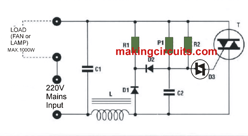
The proposed circuit can be used to alter the speed of one or more celing fans or bulbs up to a maximum power of 1000 watts by changing the volume of power applied from the load itself.

The adjustment calibration is incredibly constant and steady on account of an exclusive polarization circuit which lowers the annoying effect of hysteresis found in just about all electronic fan regulators
to practically zero .

The circuit comes with a unique LC filter that significantly decreases the diffusion of RF interfernce.

simple fan regulator circuit 220V

It is additionally advised never to make an effort to employ this fan regulator circuit with fluorescents lamps.
It is preferable if you make use of the circuit with optimum power, to place a heat sink on the TRIAC T1 in order to lengthen the life of the circuit.

Parts list for this simple yet very efficient fan regulator circuit

All resistors are 1/4 watt 5% rated unless otherwise mentioned
opposite.
Rl = 33K
R2 = 560K
Pl = 220Kohms.
CI = 0.1 μF 400 V.
C2 = 0.33 yF 100 V.
D1-1N4007
D2-1N4007
D3 = Diac DB-3
LI = Coil on ferrite
Fl = Ferrite 8 X 50mm
T1 = TRIAC 400V8A.
WARNING ! CIRCUIT WORKS WITH 230 VOLT. HANDLE WITH UTMOST CAUTION !


PCB Layout for the above explained simple 220V fan regulator circuit


fan regulator PCB layout 220V

You'll also like:

  • 1.  Zero Crossing Detector Circuit
  • 2.  TL783 High-voltage Adjustable Regulator
  • 3.  Two Transistor Voltage Doubler Circuit
  • 4.  120V 220V Over Voltage and Under Voltage Cut OFF Circuit Explained
  • 5.  High Current IC 555 Voltage Doubler Circuit
  • 6.  IC 7812, 7805 Current Booster Circuit

About Admin

Hey friends, Thanks a bunch for stopping by this site! I am an engineer with a Bachelor of Engineering in Electronics and Telecommunication. One of my passions is gathering information from all sorts of electronics books and tutorials. I then take that information and compile it into a language that is super easy to understand. My goal is to make those complex electronics circuit concepts and technical terms much more accessible for all the new and budding electronics engineers out there. I can also design customized circuit diagrams as required by the users.
If you have any questions related to this field, please do not hesitate to drop a comment! I am always here and ready to help you out with any queries you might have. I cannot wait to hear from you!

Reader Interactions

Leave a Reply Cancel reply

Your email address will not be published. Required fields are marked *

Primary Sidebar

Categories

  • 3 Phase (4)
  • 8051 Microcontroller (1)
  • Arduino (11)
  • Audio and Amplifier (102)
  • Automation (8)
  • Battery Chargers (64)
  • Bicycle Projects (4)
  • Car and Motorcycle Projects (39)
  • Datasheets (10)
  • DIY Projects (5)
  • Electrical (15)
  • Free Energy (6)
  • Games Projects (2)
  • High Voltage (14)
  • Hobby Projects (30)
  • Household Circuits (2)
  • IC 555 Circuits (4)
  • Ignition Circuits (2)
  • Indicators (50)
  • Infrared (6)
  • Inverter Circuits (29)
  • Lights and Lamps (97)
  • Medical (8)
  • Meter and Tester Circuits (38)
  • Motor Driver (17)
  • New Circuits (56)
  • Oscillators (30)
  • Pets and Pests (5)
  • Power supply (81)
  • Protection Circuits (25)
  • PWM (8)
  • Remote Control (20)
  • Security and Alarm Circuit (48)
  • Sensors and Detectors (66)
  • Signal Processor (23)
  • Solar Controller Circuits (61)
  • SSR (3)
  • Temperature Controller (20)
  • Timer (25)
  • Transformerless (7)
  • Transmitters (12)
  • Tutorials (45)
  • UPS (2)
  • Voltage Regulators (57)
  • Water Sensor and Controller (29)
  • Home
  • Privacy Policy
  • Contact
  • Disclaimer
  • Copyright

© 2025 · Making Easy Circuits