• Skip to main content
  • Skip to primary sidebar

Making Easy Circuits

Learn and build electronic circuits

You are here: Home / Audio and Amplifier / How to Make a 3.7 V Class-D Speaker Amplifier for Differential Analog Input

How to Make a 3.7 V Class-D Speaker Amplifier for Differential Analog Input

Last Updated on November 16, 2024 by Admin Leave a Comment

A class D amplifier is actually a category of amplifier through which the power devices (mosfets and BJTs) are controlled like switches.
The connected output devices in such amplifier circuits either turn fully ON or fully OFF, but never switch between other undefined levels being sure minimal heat dissipation and highest effectiveness from the devices. The functioning associated with these amplifier circuits might be known given below:
An opamp based comparator is available whose inputs are given with two signals, one is the music signal which ought to be heightened although the other is a sample high frequency triangle wave signal.
The opamp is forced to compare and evaluate the music signal with the sample triangle waves and generate an output which can be believed to be precisely proportionate as well as in tandem to the original music signal but in a PWM or a pulse width modulated form.
This music equivalent PWM is more amplified by the adjoining power mosfet or BJT stages to be able to reproduce a crystal clear music which might be a precise replica of the fed music and accomplished without much heating up of the mosfets. This enables relatively lower amps to be used than the standard form of amplifiers available other categories for example class A/B/C etc.
One such IC which is supposed to carry out a class D type of amplification is the IC BD5460 which would not even need an external choke LC filter for the procedures. Generally an inductor filter turns into important mostly with class D amplifier topologies for lessening the followed harmonics and equivalent disruptions.
The chip evolves into preferably suited to mini handheld audio devices for instance in cellphones, IPods, Ipads, FM radios etc.
The IC is stipulated with an output power of about 2 watts at 3.7V. The range of the input power could possibly be from 2.5 V to 6.5 V DC.
The IC as well likes other built-in benefits like a standby function, short circuit protection, thermal shutdown and under voltage lockout function.
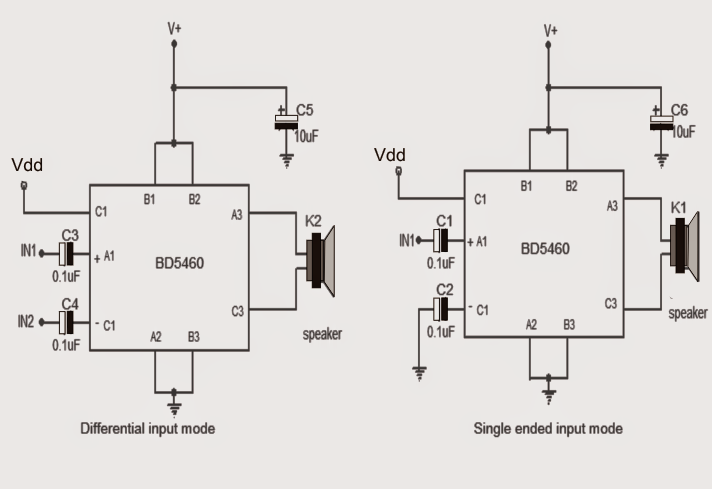
A number of class D amplifier circuits making use of the IC BD5460 could be observed in this article diagrams. The left hand side design is differential input based amplifier, while the right hand side represents a single ended topology. All the 0.1uF capacitors are set up as input decoupling filters.

BD5460 1
A lot more information regarding the IC BD BD5460 could be obtained from the following datasheet of the IC.

BD5460GUL


BD5460 2

You'll also like:

  • 1.  Simple Electronic Organ Circuit
  • 2.  Bass Treble Tone Control Circuits – 3 Designs Discussed
  • 3.  Simple Preamplifier Circuit
  • 4.  Simple Microphone (MIC) Amplifier Circuits
  • 5.  Subwoofer Amplifier Circuit – High Power
  • 6.  How to Build a Stereo headphone amplifier

About Admin

Hey friends, Thanks a bunch for stopping by this site! I am an engineer with a Bachelor of Engineering in Electronics and Telecommunication. One of my passions is gathering information from all sorts of electronics books and tutorials. I then take that information and compile it into a language that is super easy to understand. My goal is to make those complex electronics circuit concepts and technical terms much more accessible for all the new and budding electronics engineers out there. I can also design customized circuit diagrams as required by the users.
If you have any questions related to this field, please do not hesitate to drop a comment! I am always here and ready to help you out with any queries you might have. I cannot wait to hear from you!

Reader Interactions

Leave a Reply Cancel reply

Your email address will not be published. Required fields are marked *

Primary Sidebar

Categories

  • 3 Phase (4)
  • 8051 Microcontroller (1)
  • Arduino (11)
  • Audio and Amplifier (102)
  • Automation (8)
  • Battery Chargers (64)
  • Bicycle Projects (4)
  • Car and Motorcycle Projects (39)
  • Datasheets (10)
  • DIY Projects (5)
  • Electrical (15)
  • Free Energy (6)
  • Games Projects (2)
  • High Voltage (14)
  • Hobby Projects (30)
  • Household Circuits (2)
  • IC 555 Circuits (5)
  • Ignition Circuits (2)
  • Indicators (50)
  • Infrared (6)
  • Inverter Circuits (29)
  • Lights and Lamps (97)
  • Medical (8)
  • Meter and Tester Circuits (38)
  • Motor Driver (17)
  • New Circuits (56)
  • Oscillators (30)
  • Pets and Pests (5)
  • Power supply (80)
  • Protection Circuits (25)
  • PWM (9)
  • Remote Control (20)
  • Security and Alarm Circuit (48)
  • Sensors and Detectors (66)
  • Signal Processor (23)
  • Solar Controller Circuits (62)
  • SSR (3)
  • Temperature Controller (20)
  • Timer (25)
  • Transformerless (7)
  • Transmitters (12)
  • Tutorials (45)
  • UPS (2)
  • Voltage Regulators (57)
  • Water Sensor and Controller (29)
  • Home
  • Privacy Policy
  • Contact
  • Disclaimer
  • Copyright

© 2025 · Making Easy Circuits