The publish details the simple operational concept of brushless DC motors also known as BLDC motor.
In our standard brushed motors brushes are widely used to with the intention to switch the central moving rotor with regards to the surrounding stationery permanent magnet stator. Brushes turn out to be crucial simply because the rotor is created making use of electromagnets that requires power to function but mainly because it also needs to rotate things develop into clumsy and brushes become the only option for providing power to the rotating electromagnetic rotor.
On the other hand in Brushless DC motors or BLDC motors we certainly have a stationery central stator and a surrounding circular rotor. The stator consists of a couple of electromagnets while the rotor has permanent magnets affixed across its perimeter at a particular determined positions.
The mechanism also offers a Hall impact sensor that is definitely set up in order to feel the position of the rotor and its magnets with reference to the stator electromagnet and inform the data to an external switching circuit which then turns into accountable for activating/deactivating the electromagnets at the proper series or timing, affecting a rotational activity on the rotor.
The above justification might be known with the aid of the following fundamental example after which you can by means of an intricate design in the succeeding images.
We certainly have discovered and understand numerous fascinating aspects of magnets and how these devices work together.
We realize that a North Pole of the magnet attracts the south Pole of another magnet while like poles repel.
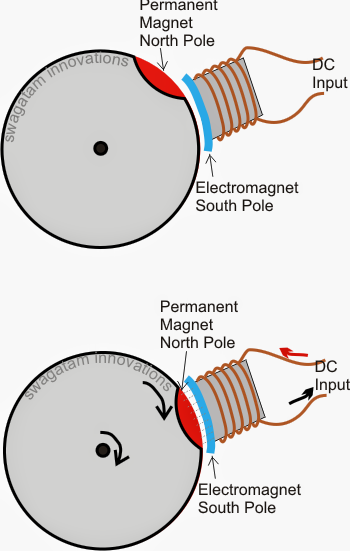
In the above revealed diagram we notice a disc with an inserted magnet at its edge (shown in red color) that could be placed with north pole facing outward, and also an electromagnet positioned at a parallel proximity to the circular edge of the disc which generates a south magnetic field when energized.
Now considering the arrangement is located as demonstrated in the first upper diagram with the electromagnet in a deactivated state.
Within this situation the moment the electromagnet is switched on with a suitable DC input it reaches and yields a south magnetic field impacting on a pulling force over the disc magnet which often forces the disc to rotate with some torque until its long lasting magnet is available in line with the electromagnets opposite lines of flux.
The above activity reflects the simple format during which BLDC principle functions.
At this point let's observe how in fact the above theory is executed utilizing Hall result sensors to be able to maintain an ongoing motion over the rotor.
The following instance diagram describes the mechanism widely:
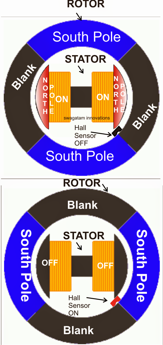
In the above diagram we essentially observe an easy BLDC rotor/stator arrangement, where the outer circular element is the rotating rotor while the central electromagnet evolves into the fixed stator.
The rotor could possibly be observed owning a few everlasting magnets set at the periphery which may have south pole as the affecting lines of flux, the central stator is a solid electromagnet which is supposed to produce the exact power of North Pole magnetic flux when energized with an external DC.
We are able to also imagine a hall sensor located near one of the corners of the inner rotor periphery. The hall impact simply sustains the magnetic field of the rotating rotor and draws the signal to a control circuit accountable of operating the stator electromagnets.
Talking about the upper position we refer to the blank area (which can be invalid of any magnetic field) of the rotor in close contact with the hall sensor maintaining it in a turned OFF condition.
At this point, the turn off signal from the hall impact informs the control circuit to turn on the electromagnets, which immediately encourages a dragging impact on the rotor south pole standing just round the corner.
At these times the South pole arrives down surging generating the necessary torque on the rotor and endeavors to align itself consistent with the north pole of the electromagnet.
In spite of this along the way the south pole of the rotor also pulls itself near to the hall sensor (as demonstrated in the lower diagram) which instantly picks up this and switches ON advising the control circuit to turn off the electromagnets.
Switching off of the electromagnets at the right moment as signaled by the hall effect sensor does not allow stalling and hampering of the rotor motion, somewhat permits it to continue with the motion through the developed torque until the earlier position starts shaping up, and until the hall sensor yet again "feels" the blank area of the rotor and gets shut OFF repeating the cycle.
The above toggling of the hall sensor appropriate to the numerous rotor positions inflicts a constant rotational motion with a toque which can be straight proportional to the stator/rotor magnetic interactions, and ofcourse the hall effect positioning.
The above conversations describes the most critical two magnet, one hall sensor mechanism.
To be able to achieve particularly higher torques more magnets and sets of electromagnets are being used in other higher effectiveness brushless motors through which several hall result sensor could be viewed for following multiple sensing of the rotor magnets to ensure that different sets of electromagnets might be switched at the desired appropriate phase.
Leave a Reply