The following article will cover a quite basic circuit for an automated 220V AC voltage stabilizer that is controlled by a few triacs and logic integrated circuits (ICs) to regulate the mains electricity levels.
Solid State is more Efficient
Because the layout is solid state, there is very little mechanical damage on the voltage switching transitions, which leads to effective voltage stability.
Learn about the entire building process of this special solid state mains voltage stabilizer.
Any piece of equipment at its output will receive good four-step voltage stabilization from the suggested setup of a triac-controlled AC voltage stabilizer.
Its efficiency is additionally improved by the absence of moving components. Learn more about this quiet operator: Power Guard.
Although helpful, the automated voltage stabilizer circuit covered in one of my earlier articles cannot independently handle the various levels of fluctuating mains voltages because of its more basic architecture.
Even though it hasn't been tried, the suggested approach seems reasonable, and if the important parts are sized correctly, it ought to function as planned.
Virtually perfect in every way, the current circuit of a triac-controlled AC voltage stabilizer performs very well.
As is customary, I developed the circuit alone. Using four distinct processes, it can precisely regulate and regulate the input mains electrical voltage.
By using triacs, the rapid (usually just 2 mS) and transient-free transitions are ensured, which are often associated with relay-type stabilizers.
Additionally, the absence of any dynamic parts results in a fully solid state and nearly permanent operation for the whole unit.
Now let's examine the circuit's operation.
WARNING: THIS CIRCUIT Could INCLUDE ALL POINTS THAT ARE AT AC MAINS POTENTIAL, MAKING IT Extremely RISKY TO Contact IN SWITCHED ON POSITION. When working with this design, extreme caution and attention are necessary. It is strongly encouraged to use a wooden plank beneath your feet. We ask that you remain away, newcomers.
Circuit Working
The following details can help one understand how the circuit operates:
The arrangement of transistors T1 through T4 allows them to perceive a steady increase in the input voltage and to conduct sequentially as the voltage climbs and vice versa.
IC 4093's gates N1 through N4 are set up as buffers. These gates are used to receive their inputs from the transistors' outputs.
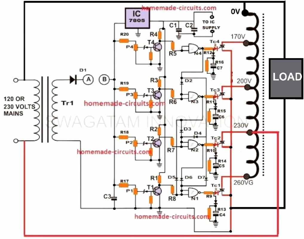
Because of the manner in which the gates are coupled to one another, depending on the input voltage threshold, only one of the gates' outputs is always operational at any one moment.
In other words, when the input voltage increases, the gates react to the transistors, and one by one, their outputs turn logic high while ensuring that the output of the preceding gate is turned off, and vice versa.
The necessary "hot" connection from the transformer is linked to the downstream equipment by applying the logic hi from the specific buffer to the gate of the corresponding SCR.
The specified triacs then choose the proper “hot” terminals of the transformer to adjust the voltage and keep the output largely stable when the voltage goes up.
Construction Tips
It just takes a few easy steps to make this triac control AC power guard circuit: obtaining the necessary components and carefully arranging them on a standard PCB.
It's very clear that the individual trying to build this circuit is somewhat knowledgeable about electronics beyond the fundamentals.
If there are a mistake in the final assembly, matters might go very badly.
To configure the device as follows, you'll need a separate external adjustable (0 to 12 volt) ubiquitous DC power supply:
Based on calculations, we can determine that if TR1's output supply of 12 volts is comparable to a 225 volt input supply, it generates 9 volts at an input of 170 volts, 13 volts at 245 volts, and 14 volts at around 260 volts.
The Circuit's Configuration and Testing Guide
Make certain the circuit is completely unplugged from the AC mains and leave the points "AB" unconnected at first.
Set the adjustable power supply's positive terminal to point "B" and its negative terminal to the circuit's common ground. Tune the power supply to 12 volts.
Now tweak P2 till LD2 is just turned on. To turn on LD1, lower the voltage to 9 and modify P1.
P3 and P4 should also be adjusted such that the corresponding LEDs are illuminated at voltages 13 and 14, respectively.
The process of setup is now finished. After disconnecting the external supply, connect points "AB" to one another.
In order to enable immediate operation, the entire unit may now be linked to the mains AC.
By providing a variable AC input through an auto transformer and examining the output with a digital multimeter, you can confirm the system's functionality.
At voltages lower than 170 volts and higher than 300 volts, this triac-controlled AC voltage stabilizer will cut off.
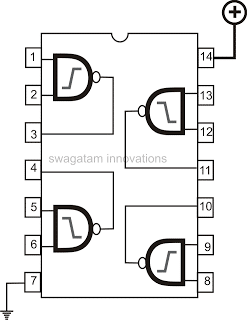
IC 4093 Internal Gate Pinout Arrangement
Parts List
The following components are needed to build this SCR control ac voltage stabilizer:
All resistors are ¼ Watt, CFR 5%, unless otherwise stated.
| Component | Details |
|---|---|
| Resistors (R5, R6, R7, R8) | 1M Ohm, ¼ watt |
| Triacs | 400 volts, 1KV rated |
| Transistors (T1, T2, T3, T4) | BC 547 |
| Zener Diodes | 3 volts, 400 mW |
| Diodes | 1N4007 |
| Presets | 10K linear |
| Resistors (R1, R2, R3, …, R20) | 1K Ohm, ¼ watt |
| Integrated Circuits (N1 to N4) | IC 4093 |
| Capacitors (C1, C2, C3) | C1, C3: 100uF, 25 volts; C2: 104, ceramic |
| Power Guard Stabilizer Transformer | "Made to order" with various output taps (e.g., 170V, 225V, 240V, 260V at 225V input or 85V, 115V, 120V, 130V at 110V AC input) |
| Transformer (TR1) | Step down transformer, 0 – 12 volts, 100 mA |
Leave a Reply