• Skip to main content
  • Skip to primary sidebar

Making Easy Circuits

Learn and build electronic circuits

You are here: Home / High Voltage / Generator Mains Power Booster Circuit

Generator Mains Power Booster Circuit

Last Updated on February 17, 2018 by Admin 33 Comments

The post describes an alternator or generator power booster circuit, Let's find out more about the .


Generator Mains Power Booster Circuit
Circuit Justification

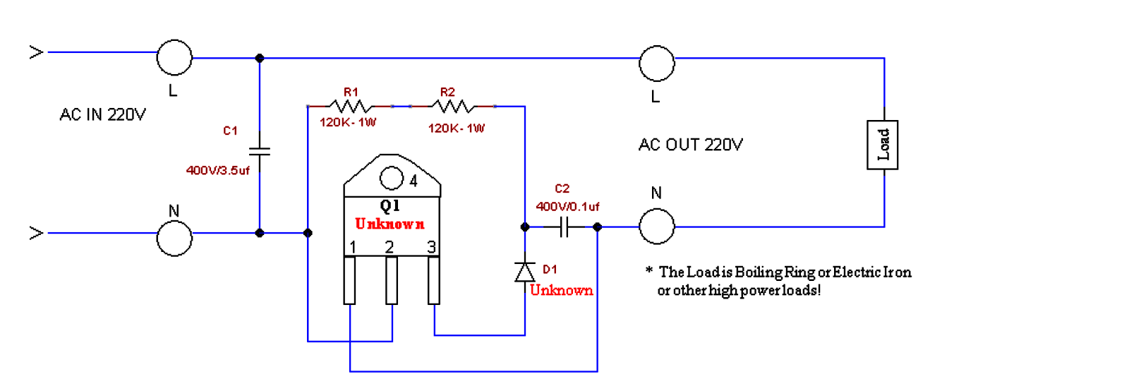
The circuit seems to be a straightforward AC voltage booster. The main part which can be to blame for providing the excess power is the high voltage capacitor C1 which charges up with each AC cycle and reverts the power by means of the switching triac into the linked load.

The load thus gets added power due to the switching high voltage capacitor by way of the triac.

The triac is usually a BTA41/600A, which replies and switches ON the moment the diac fires. The minimum voltage necessary for the diac to fire is around 30 volts.

The above idea may also be used with the following circuit which happens to be less complicated than the above and is also very much cheaper.


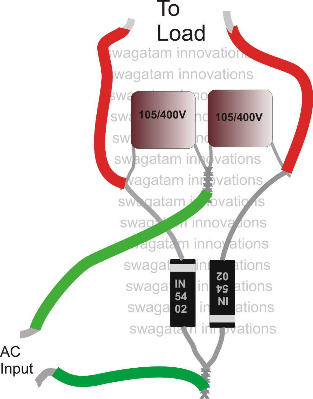
The capacitor ratings might be altered and tried as per the load, and individual choices.

However this circuit can be utilized only for heater applications such as irons, heaters, geysers, ovens, toasters, blowers, dryers, hot air gun etc.


You'll also like:

  • 1.  How to Increase Power Rating of Zener Diodes
  • 2.  Light Dimmer Circuit
  • 3.  Switching Triacs Safely using Zero Voltage (ZVS)
  • 4.  Push Button Dimmer Circuit
  • 5.  12 V To 6 V Converter Circuit
  • 6.  Solid-State ELCB Circuit using SCR and Triac

Tagged With: Booster, Generator, Mains, Power

About Admin

Hey friends, Thanks a bunch for stopping by this site! I am an engineer with a Bachelor of Engineering in Electronics and Telecommunication.

One of my passions is gathering information from all sorts of electronics books and tutorials. I then take that information and compile it into a language that is super easy to understand.

My goal is to make those complex electronics circuit concepts and technical terms much more accessible for all the new and budding electronics engineers out there.

I can also design customized circuit diagrams as required by the users.

If you have any questions related to this field, please do not hesitate to drop a comment!

I am always here and ready to help you out with any queries you might have. I cannot wait to hear from you!

Reader Interactions

Comments

Victor says:
August 28, 2025 at 1:13 pm

Please can the second circuit be used to boost inverter power?

Reply
Admin says:
August 29, 2025 at 7:51 am

It will only boost voltage, not power, and will work only for resistive loads..

Reply
Patrick says:
April 19, 2023 at 11:10 am

Please how many watts is the second circuit? I build it and is not working with my soldering iron not even to talk of iron Sir. Please I need an urgent help because this is my project topic and to be submitted soon. Thanks

Reply
Admin says:
April 27, 2023 at 10:00 am

It is a tested design and it worked for me beautifully, my soldering iron became red hot within 1 minute.
It is nothing but a simple voltage doubler circuit.
310V x 50 mA = 15 watts

Reply
Brain Moore King says:
March 16, 2023 at 11:37 am

The first circuit needs clearification
OK I want to boost power from a 600watts generator to supply my electric iron and cooker what will be the rating of the diac

Reply
INNOCENT says:
February 26, 2021 at 3:23 am

The 2nd circuit has zero vibration in all
Generator

Reply
AK says:
November 4, 2020 at 12:43 pm

The first one lacks clarity and unsure if it would work. The second one is a half-wave voltage doubler, DC output. When capacitance is small and load-current is large, the voltage will be unregulated, spiky, or contains more ripple.

Reply
Admin says:
November 16, 2020 at 9:04 pm

That’s exactly why the second circuit is recommended for resistive loads….

Reply
Admin says:
April 29, 2023 at 8:53 am

Hello Patrick, the first circuit is not yet tested by me so I am not sure about it.

Reply
Patrick says:
April 27, 2023 at 11:32 am

Good morning Sir, is the first circuit working? Because I designed it but the output voltage is reading 110v

Reply
View Older Comments

Leave a Reply Cancel reply

Your email address will not be published. Required fields are marked *

Primary Sidebar

Categories

  • 3 Phase
  • 8051 Microcontroller
  • Arduino
  • Audio and Amplifier
  • Automation
  • Battery Chargers
  • Bicycle Projects
  • Car and Motorcycle Projects
  • Datasheets
  • DIY Projects
  • Electrical
  • Free Energy
  • Games Projects
  • High Voltage
  • Hobby Projects
  • Household Circuits
  • IC 555 Circuits
  • Ignition Circuits
  • Indicators
  • Infrared
  • Inverter Circuits
  • Lights and Lamps
  • Medical
  • Meter and Tester Circuits
  • Motor Driver
  • New Circuits
  • Oscillators
  • Pets and Pests
  • Power supply
  • Protection Circuits
  • PWM
  • Remote Control
  • Security and Alarm Circuit
  • Sensors and Detectors
  • Signal Processor
  • Solar Controller Circuits
  • SSR
  • Temperature Controller
  • Timer
  • Transformerless
  • Transmitters
  • Tutorials
  • UPS
  • Voltage Regulators
  • Water Sensor and Controller
  • Home
  • Privacy Policy
  • Contact
  • Disclaimer
  • Copyright

© 2025 · Making Easy Circuits