• Skip to main content
  • Skip to primary sidebar

Making Easy Circuits

Learn and build electronic circuits

You are here: Home / Medical / How to Build a Heart Rate Monitor, Alarm Circuit

How to Build a Heart Rate Monitor, Alarm Circuit

Last Updated on November 17, 2024 by Admin Leave a Comment

The publish explores a straightforward circuit which can be employed for supervising the essential heart rate of a patient (senior citizen), the circuit furthermore consists of an alarm for showing the condition.
In the earlier article we picked up to create a heart rate sensor circuit with processor, which might be properly utilized in the offered important heart rate alarm circuit.
The application listed here is for reference design purposes only and is not meant for any life-saving or medical-monitoring use.

Heart Rate processor indicator Circuit
Heart Rate Monitor, Alarm Circuit
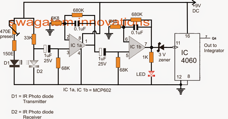
Talking about the diagrams above, you can easily observe a few circuit stages, the first being the heart rate sensor/processor with an built-in frequency multiplier, while the second by means of an integrator, comparator.
The upper signal processor design continues to be widely described in the prior submit, the further voltage multiplier that is certainly been incorporated to the processor utilizes the IC 4060 for boosting the comparatively less quickly heart rates into a consequently differing high frequency rate.
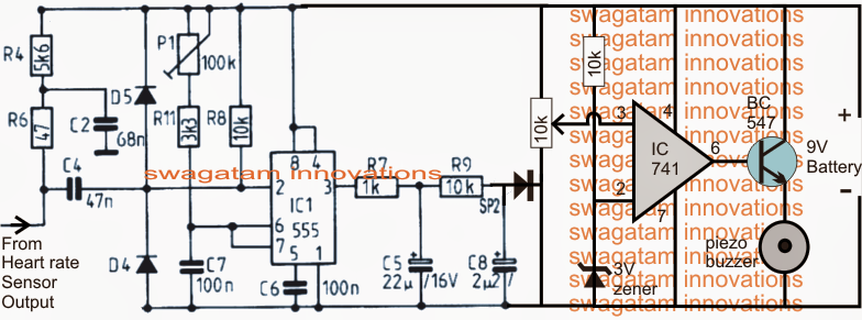
The above correspondingly changing high frequency heart pulse rate from pin7 of IC 4060 is given to the input of an integrator whose task is to transfer the digitally varying frequency into a equally varying exponential analogue signal.
Lastly this analogue voltage is placed on the non inverting input of a Ic 741 comparator. The comparator is set by means of the connected 10k preset such that the voltage level at pin3 remains just below the reference voltage at pin2 when the heart rate is in the vicinity of the secure region.
In spite of this if the heart rate is likely to boost over the crucial region, a correspondingly higher voltage level is produced at pin3 which exceeds the pin2 reference level triggering the output of the opamp to go high and sound the alarm.
The above set up only displays and alarms concerning the higher important heart rate, to be able to attain a two way checking, which means to get an alarm for both higher and lower crucial heart rates...the second circuit consisting the IC555 and IC741 might be completely removed and restored with a regular IC LM567 circuit set to maintain its output low at the protected pulse rate, and go high at the up or down critical rates.

You'll also like:

  • 1.  Home Intruder Alarm Circuit
  • 2.  How to Make a Power ON Alarm with Auto OFF Circuit
  • 3.  Anti-Burglar Home Lighting Circuit
  • 4.  Simple Electronic Siren Circuit
  • 5.  Vibration Activated Alarm Circuit
  • 6.  Basic Circuit for Making a Car Burglar Alarm

About Admin

Hey friends, Thanks a bunch for stopping by this site! I am an engineer with a Bachelor of Engineering in Electronics and Telecommunication. One of my passions is gathering information from all sorts of electronics books and tutorials. I then take that information and compile it into a language that is super easy to understand. My goal is to make those complex electronics circuit concepts and technical terms much more accessible for all the new and budding electronics engineers out there. I can also design customized circuit diagrams as required by the users.
If you have any questions related to this field, please do not hesitate to drop a comment! I am always here and ready to help you out with any queries you might have. I cannot wait to hear from you!

Reader Interactions

Leave a Reply Cancel reply

Your email address will not be published. Required fields are marked *

Primary Sidebar

Categories

  • 3 Phase (4)
  • 8051 Microcontroller (1)
  • Arduino (11)
  • Audio and Amplifier (102)
  • Automation (8)
  • Battery Chargers (64)
  • Bicycle Projects (4)
  • Car and Motorcycle Projects (39)
  • Datasheets (10)
  • DIY Projects (5)
  • Electrical (15)
  • Free Energy (6)
  • Games Projects (2)
  • High Voltage (14)
  • Hobby Projects (30)
  • Household Circuits (2)
  • IC 555 Circuits (5)
  • Ignition Circuits (2)
  • Indicators (50)
  • Infrared (6)
  • Inverter Circuits (29)
  • Lights and Lamps (97)
  • Medical (8)
  • Meter and Tester Circuits (38)
  • Motor Driver (17)
  • New Circuits (56)
  • Oscillators (30)
  • Pets and Pests (5)
  • Power supply (80)
  • Protection Circuits (25)
  • PWM (9)
  • Remote Control (20)
  • Security and Alarm Circuit (48)
  • Sensors and Detectors (66)
  • Signal Processor (23)
  • Solar Controller Circuits (62)
  • SSR (3)
  • Temperature Controller (20)
  • Timer (25)
  • Transformerless (7)
  • Transmitters (12)
  • Tutorials (45)
  • UPS (2)
  • Voltage Regulators (57)
  • Water Sensor and Controller (29)
  • Home
  • Privacy Policy
  • Contact
  • Disclaimer
  • Copyright

© 2025 · Making Easy Circuits