• Skip to main content
  • Skip to primary sidebar

Making Easy Circuits

Learn and build electronic circuits

You are here: Home / Timer / Making Delay Timers using NOT gates IC 4049

Making Delay Timers using NOT gates IC 4049

Last Updated on January 10, 2018 by Admin Leave a Comment

The post explains how accurate delay timers using NOT gates can be built easily with the help of ICs such as IC 4049 and generate reproducible delay features from these configurations.

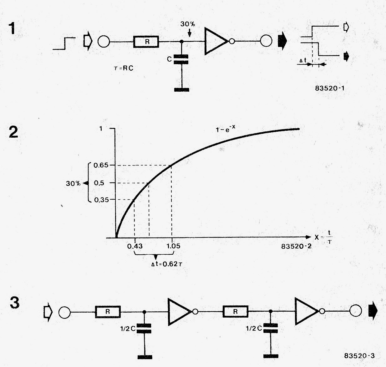
There are several situations when a switching delay is necessary. One of the ways of accomplishing this is to utilize an RC network and an inverter (see figure 1). This is certainly pretty functional and apparent as there are frequently a few gates 'left over' within a circuit. Sadly, each electronic component includes a certain threshold and thus it is practically impossible to figure out the delay accurately ahead of time. However a considerable enhancement may be accomplished by hooking up a couple of inverter/ RC networks in series as demonstrated in figure 3. The minimal tolerance voltage of the inverter in figure 1 is 1 / 2 the supply voltage and possesses a tolerance of 30%. Figure 2 exhibits the signal input on the gate. lf this specific input is involving Uc =0.35 UD and Uc = 0.65 Ub the inverter may possibly ponder over it either logic 'O' or 'l’ ! These voltages happen whenever a capacitor is charged via a resistor soon after an interval of 0.43 T and 1.057 correspondingly. (T is the time constant in the circuit and it is identical to R x C). The minimal tolerance voltage UC = 0.5 Ub is attained soon after this period of t = 0.69 T.

When the two inverters and RC networks of figure 3 are employed, each one RC network need to generate exactly the same delay, corresponding to half the overall value of figure 1. The entire delay are going to be 1/2 x 0.43 T+1/2 x 1.05 T=0.74 T in its most severe circumstance! This can be a great deal nearer to the minimal value of 0.69 T,

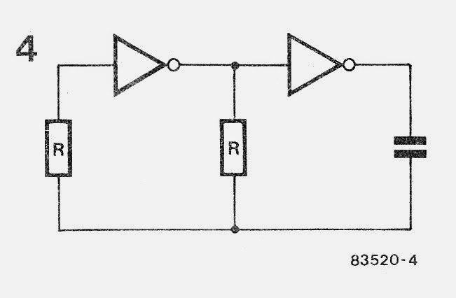
The foregoing must inform you the reason why the simple delay timer circuit of figure 4 offers this kind of persistently reproducible outcomes. On the other hand, to get truly acceptable operations, CMOS inverters should be used. This is because these types of gates possess a tolerance value of about 50 % the supply voltage. Additionally, their output are invariably either zero or the supply voltage. Schmitt triggers must not be applied! lf the delay periods utilizing 4000 series CMOS are normally found to be too prolonged the different 74HCXX series may be used. These are generally pin and function agreeable to the 74LSXX series and just simply as speedy!

Making Delay Timers using NOT gates IC 4049


simple delay timer circuit2

You'll also like:

  • 1.  How to Build a Simple Industrial Delay Timer Circuits
  • 2.  Timer Controlled Mobile Phone Charger Circuit
  • 3.  How to Build a Timer Circuit with Auto Pause and Resume During Power Failures
  • 4.  Simple Delay ON Timer Circuit using Two BC547 Tansistors
  • 5.  How to Make a Sequential Delay Timer Circuit
  • 6.  Dark Room Timer Circuit

About Admin

Hey friends, Thanks a bunch for stopping by this site! I am an engineer with a Bachelor of Engineering in Electronics and Telecommunication. One of my passions is gathering information from all sorts of electronics books and tutorials. I then take that information and compile it into a language that is super easy to understand. My goal is to make those complex electronics circuit concepts and technical terms much more accessible for all the new and budding electronics engineers out there. I can also design customized circuit diagrams as required by the users.
If you have any questions related to this field, please do not hesitate to drop a comment! I am always here and ready to help you out with any queries you might have. I cannot wait to hear from you!

Reader Interactions

Leave a Reply Cancel reply

Your email address will not be published. Required fields are marked *

Primary Sidebar

Categories

  • 3 Phase (4)
  • 8051 Microcontroller (1)
  • Arduino (11)
  • Audio and Amplifier (102)
  • Automation (8)
  • Battery Chargers (64)
  • Bicycle Projects (4)
  • Car and Motorcycle Projects (39)
  • Datasheets (10)
  • DIY Projects (5)
  • Electrical (15)
  • Free Energy (6)
  • Games Projects (2)
  • High Voltage (14)
  • Hobby Projects (30)
  • Household Circuits (2)
  • IC 555 Circuits (5)
  • Ignition Circuits (2)
  • Indicators (50)
  • Infrared (6)
  • Inverter Circuits (29)
  • Lights and Lamps (97)
  • Medical (8)
  • Meter and Tester Circuits (38)
  • Motor Driver (17)
  • New Circuits (56)
  • Oscillators (30)
  • Pets and Pests (5)
  • Power supply (80)
  • Protection Circuits (25)
  • PWM (9)
  • Remote Control (20)
  • Security and Alarm Circuit (48)
  • Sensors and Detectors (66)
  • Signal Processor (23)
  • Solar Controller Circuits (62)
  • SSR (3)
  • Temperature Controller (20)
  • Timer (25)
  • Transformerless (7)
  • Transmitters (12)
  • Tutorials (45)
  • UPS (2)
  • Voltage Regulators (57)
  • Water Sensor and Controller (29)
  • Home
  • Privacy Policy
  • Contact
  • Disclaimer
  • Copyright

© 2025 · Making Easy Circuits