• Skip to main content
  • Skip to primary sidebar

Making Easy Circuits

Learn and build electronic circuits

You are here: Home / Remote Control / How to Make a Remote Controlled Pulley Hoist Mechanism Circuit Part-2

How to Make a Remote Controlled Pulley Hoist Mechanism Circuit Part-2

Last Updated on February 17, 2018 by Admin Leave a Comment

The earlier conversation described precisely how the pulley hoist mechanism ought to be set, subsequent, according to the demand the motor is meant to be managed by means of a remote control circuit.
These days RF remote modules might be obtained fairly inexpensively and very easily from the local electronic shops, so it's suggested to buy one rather than trying to make one.
It is possible to keep reading about it in this Submit
For hard core enthusiasts who desire to develop the whole thing with their own hands, a relevant circuit design is mentioned within this Article
Once you have acquired ready Rx, Tx modules, you will discover the receiver Rx units of these RF modules acquiring built-in relays nevertheless these relays could possibly be quite inferior with their load handling capacity thereby ought to be reinforced with external relays, particularly when the load is a high current type similar to the existing application.
Ideally buy a two-relay RF module simply because we require just two relays for managing the reverse forward motions of the motor. Common illustration of a two relay module could be observed in the following image.


two2Brelay2BRF2Bmodule2Bimage


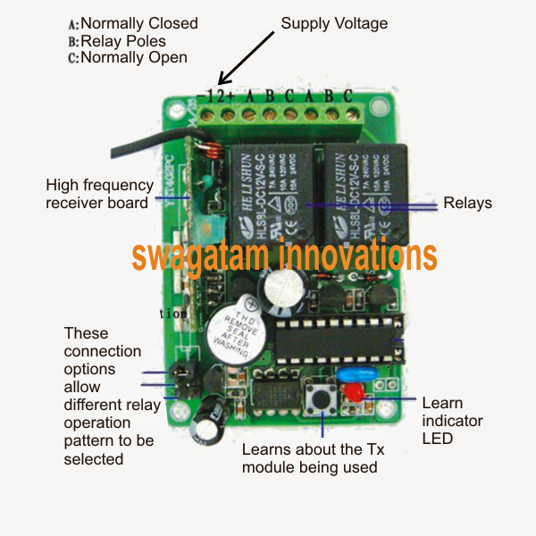
The enclosed relays in the Rx PCB will function as a reaction to the pressing of the associated buttons on the Tx transmitter module, so it's all about tracing out the N/O, N/C and the poles of these two relays and wire them up with the external heavy duty relays for enforcing the preferred motor reverse forward motions.
The following diagram thoroughly details the wiring layout of the relays, once the wiring is finished in accordance with the demonstrated diagram one of the buttons may cause the motor to rotate clockwise while pressing the other would certainly flip the motor direction anticlockwise.


remote2Bcontrol2Brelay2Bwiring2Bdetails
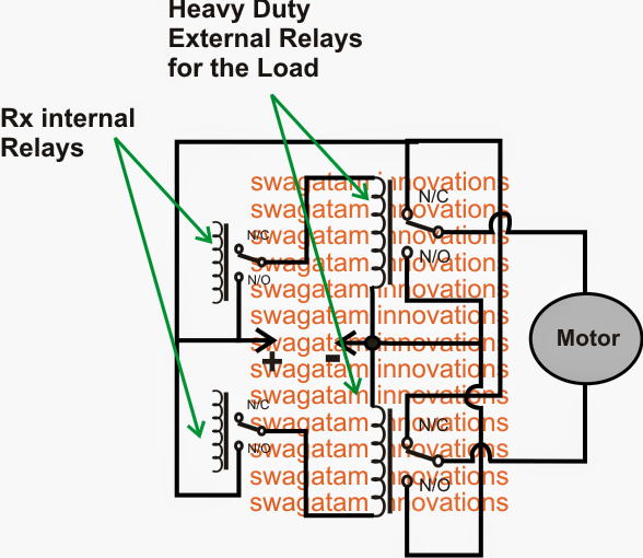
When no buttons are functional the motor would stationery. The motor would wind or unwind the pulley ropes as long as the appropriate buttons of the Tx is held pressed by the user and would halt once produced.
On the other hand, you could look at having fun with the in-built Rx modules "relay operation selector" connections by inserting the plugs properly until the needed spec are located whereby the relay is permitted to toggle ON/OFF with each and every alternate press of the Tx buttons along with the user do not have to maintain the pertinent Tx button pressed constantly for performing the meant motor rotations.

You'll also like:

  • 1.  IR Remote Controlled Door Lock Circuit
  • 2.  How to build a Infrared Remote Control Security Lock Circuit for Automotive Applications
  • 3.  Wireless Lamp using an RF Disturbance Circuit
  • 4.  How to Build a Remote Controlled Night Lamp Circuit with Timer
  • 5.  How to Make a Remote Controlled Pulley Hoist Mechanism Circuit Part-1
  • 6.  How to Make a Ultrasonic Remote Control Circuit

About Admin

Hey friends, Thanks a bunch for stopping by this site! I am an engineer with a Bachelor of Engineering in Electronics and Telecommunication. One of my passions is gathering information from all sorts of electronics books and tutorials. I then take that information and compile it into a language that is super easy to understand. My goal is to make those complex electronics circuit concepts and technical terms much more accessible for all the new and budding electronics engineers out there. I can also design customized circuit diagrams as required by the users.
If you have any questions related to this field, please do not hesitate to drop a comment! I am always here and ready to help you out with any queries you might have. I cannot wait to hear from you!

Reader Interactions

Leave a Reply Cancel reply

Your email address will not be published. Required fields are marked *

Primary Sidebar

Categories

  • 3 Phase (4)
  • 8051 Microcontroller (1)
  • Arduino (11)
  • Audio and Amplifier (102)
  • Automation (8)
  • Battery Chargers (64)
  • Bicycle Projects (4)
  • Car and Motorcycle Projects (39)
  • Datasheets (10)
  • DIY Projects (5)
  • Electrical (15)
  • Free Energy (6)
  • Games Projects (2)
  • High Voltage (14)
  • Hobby Projects (30)
  • Household Circuits (2)
  • IC 555 Circuits (5)
  • Ignition Circuits (2)
  • Indicators (50)
  • Infrared (6)
  • Inverter Circuits (29)
  • Lights and Lamps (97)
  • Medical (8)
  • Meter and Tester Circuits (38)
  • Motor Driver (17)
  • New Circuits (56)
  • Oscillators (30)
  • Pets and Pests (5)
  • Power supply (80)
  • Protection Circuits (25)
  • PWM (9)
  • Remote Control (20)
  • Security and Alarm Circuit (48)
  • Sensors and Detectors (66)
  • Signal Processor (23)
  • Solar Controller Circuits (62)
  • SSR (3)
  • Temperature Controller (20)
  • Timer (25)
  • Transformerless (7)
  • Transmitters (12)
  • Tutorials (45)
  • UPS (2)
  • Voltage Regulators (57)
  • Water Sensor and Controller (29)
  • Home
  • Privacy Policy
  • Contact
  • Disclaimer
  • Copyright

© 2025 · Making Easy Circuits