• Skip to main content
  • Skip to primary sidebar

Making Easy Circuits

Learn and build electronic circuits

You are here: Home / Audio and Amplifier / Simple Buzzer Circuit using 8 Ohm Speaker

Simple Buzzer Circuit using 8 Ohm Speaker

Last Updated on November 16, 2024 by Admin Leave a Comment

The discussed circuit produces sounds which resembles to an authentic buzzer. It operates using just two integrated circuits and a minimal number of components.

high power buzzer circuit diagram using loudspeaker.
Just a quick note: Remember, to link pin number 4 of the IC 555 to the positive power supply.

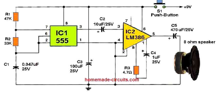
When you press the switch S1, the capacitor C1 starts to get power through the resistors R1 and R2. This action sets off pin 2 of the 555 timer, IC1.

Then IC1 makes pin 7 go low, which makes the capacitor lose its charge through R2. This process keeps going as long as you keep S1 pressed.

The signal from IC1 (at pin 3) changes back and forth with the capacitors charge and discharge cycles, creating a sound wave for IC2. IC2 is an LM386 audio amplifier which makes the sound louder.

You use a speaker to copy the sound from IC1 that sounds just like a real buzzer. If you want the buzz to be lower pitched, try using a bigger capacitor for C1 like 0.1 uF.

To make the setup more stable, you can connect a 47 uF capacitor from pin 7 of IC2 to the ground.

You'll also like:

  • 1.  250 Watt MOSFET Power Amplifier Circuit
  • 2.  How to Make a 3.7 V Class-D Speaker Amplifier for Differential Analog Input
  • 3.  How to Build a DIY Contact MIC Circuit
  • 4.  Simple Bird Sound Generator Circuit
  • 5.  36 Watt BTL Power Amplifier Circuit using IC TDA1562Q
  • 6.  Theremin Circuit

About Admin

Hey friends, Thanks a bunch for stopping by this site! I am an engineer with a Bachelor of Engineering in Electronics and Telecommunication. One of my passions is gathering information from all sorts of electronics books and tutorials. I then take that information and compile it into a language that is super easy to understand. My goal is to make those complex electronics circuit concepts and technical terms much more accessible for all the new and budding electronics engineers out there. I can also design customized circuit diagrams as required by the users.
If you have any questions related to this field, please do not hesitate to drop a comment! I am always here and ready to help you out with any queries you might have. I cannot wait to hear from you!

Reader Interactions

Leave a Reply Cancel reply

Your email address will not be published. Required fields are marked *

Primary Sidebar

Categories

  • 3 Phase (4)
  • 8051 Microcontroller (1)
  • Arduino (11)
  • Audio and Amplifier (102)
  • Automation (8)
  • Battery Chargers (64)
  • Bicycle Projects (4)
  • Car and Motorcycle Projects (39)
  • Datasheets (10)
  • DIY Projects (5)
  • Electrical (15)
  • Free Energy (6)
  • Games Projects (2)
  • High Voltage (14)
  • Hobby Projects (30)
  • Household Circuits (2)
  • IC 555 Circuits (5)
  • Ignition Circuits (2)
  • Indicators (50)
  • Infrared (6)
  • Inverter Circuits (29)
  • Lights and Lamps (97)
  • Medical (8)
  • Meter and Tester Circuits (38)
  • Motor Driver (17)
  • New Circuits (56)
  • Oscillators (30)
  • Pets and Pests (5)
  • Power supply (80)
  • Protection Circuits (25)
  • PWM (9)
  • Remote Control (20)
  • Security and Alarm Circuit (48)
  • Sensors and Detectors (66)
  • Signal Processor (23)
  • Solar Controller Circuits (62)
  • SSR (3)
  • Temperature Controller (20)
  • Timer (25)
  • Transformerless (7)
  • Transmitters (12)
  • Tutorials (45)
  • UPS (2)
  • Voltage Regulators (57)
  • Water Sensor and Controller (29)
  • Home
  • Privacy Policy
  • Contact
  • Disclaimer
  • Copyright

© 2025 · Making Easy Circuits