• Skip to main content
  • Skip to primary sidebar

Making Easy Circuits

Learn and build electronic circuits

You are here: Home / Voltage Regulators / 12V to 24V Voltage Doubler Circuit using IC 4093

12V to 24V Voltage Doubler Circuit using IC 4093

Last Updated on November 17, 2024 by Admin Leave a Comment

This 12V to 24V Voltage Doubler Circuit can increase the operating voltage by as much as 200% and provides an output current capacity between 10 to 20 mA.

12V to 24V Voltage Doubler Circuit using IC 4093

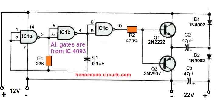
A CD4093 dual-input NAND Schmitt-trigger CMOS IC's gates, IC1a and IC1b, have been used to construct a squarewave oscillator circuit.

The gate IC1c is configured to act as an output buffer. The matching transistors Q1 and Q2 are powered by the buffered output of IC1.

The square wave output at the transistor emitters powers the voltage-doubler circuit, that consists of D1, D2, C2, and C3. This produces a two times stepped up output.

Assuming a 12 volt supply, the voltage boosting circuit will generate approximately 18.5 volts at around twenty mA and 24 volts at roughly ten mA.

Always keep in mind to link the additional, empty gate's inputs to the circuit's ground line.

You'll also like:

  • 1.  5KVA Voltage Stabilizer Circuit
  • 2.  TL783 High-voltage Adjustable Regulator
  • 3.  3V to 5V Boost Circuit for Battery Charging and LED Driver Applications
  • 4.  Simple 0.6V to 12V Boost Converter Circuit
  • 5.  Customizable Fixed Voltage Regulator Circuit using Opamp
  • 6.  Simple Fluorescent Lamp Dimmer Circuit

About Admin

Hey friends, Thanks a bunch for stopping by this site! I am an engineer with a Bachelor of Engineering in Electronics and Telecommunication. One of my passions is gathering information from all sorts of electronics books and tutorials. I then take that information and compile it into a language that is super easy to understand. My goal is to make those complex electronics circuit concepts and technical terms much more accessible for all the new and budding electronics engineers out there. I can also design customized circuit diagrams as required by the users.
If you have any questions related to this field, please do not hesitate to drop a comment! I am always here and ready to help you out with any queries you might have. I cannot wait to hear from you!

Reader Interactions

Leave a Reply Cancel reply

Your email address will not be published. Required fields are marked *

Primary Sidebar

Categories

  • 3 Phase (4)
  • 8051 Microcontroller (1)
  • Arduino (11)
  • Audio and Amplifier (102)
  • Automation (8)
  • Battery Chargers (64)
  • Bicycle Projects (4)
  • Car and Motorcycle Projects (39)
  • Datasheets (10)
  • DIY Projects (5)
  • Electrical (15)
  • Free Energy (6)
  • Games Projects (2)
  • High Voltage (14)
  • Hobby Projects (30)
  • Household Circuits (2)
  • IC 555 Circuits (4)
  • Ignition Circuits (2)
  • Indicators (50)
  • Infrared (6)
  • Inverter Circuits (29)
  • Lights and Lamps (97)
  • Medical (8)
  • Meter and Tester Circuits (38)
  • Motor Driver (17)
  • New Circuits (56)
  • Oscillators (30)
  • Pets and Pests (5)
  • Power supply (81)
  • Protection Circuits (25)
  • PWM (8)
  • Remote Control (20)
  • Security and Alarm Circuit (48)
  • Sensors and Detectors (66)
  • Signal Processor (23)
  • Solar Controller Circuits (61)
  • SSR (3)
  • Temperature Controller (20)
  • Timer (25)
  • Transformerless (7)
  • Transmitters (12)
  • Tutorials (45)
  • UPS (2)
  • Voltage Regulators (57)
  • Water Sensor and Controller (29)
  • Home
  • Privacy Policy
  • Contact
  • Disclaimer
  • Copyright

© 2025 · Making Easy Circuits