• Skip to main content
  • Skip to primary sidebar

Making Easy Circuits

Learn and build electronic circuits

You are here: Home / Water Sensor and Controller / Simple Water Sensor Circuit with Alarm

Simple Water Sensor Circuit with Alarm

Last Updated on November 17, 2024 by Admin Leave a Comment

Water sensor is a little unit which is used to give an audible alarm when a hose of the washing machine has burst or when it starts to rain, so that you can save the washing machine from being rain drenched, or it can give an alarm to call you to the bathroom when the bathwater is needed to turn on.

Undoubtedly you can think of some more utilization of water sensor.

You can power the circuit from a 9 V PP3 battery. Since the current consumption is very low, chances are it will last for a year at least. After a year the battery loses its ability of self-discharge.

Therefore, after a year the unreliable battery must be replaced. The water detector unit is made up of a sensor, an R-S bi-stable, an oscillator and a sensor stage which works as the alarm buzzer.

How the Water Sensor Fabricated

The sensor is made of a waste-piece of wiring board which is of 40x20 mm in size. One needs to connect all odds and all even tracks together with the wire link in such a way so that 1 connects to 3 to 5, on the other hand 2 connects to 4 to 6.

You need to protect the tracks with tin to prevent them from corrosion. The resistance between two sets of tracks stays high when the board remains dry. However, when the board is wet, a sharp decline in resistance is observed.

How the Circuit Works
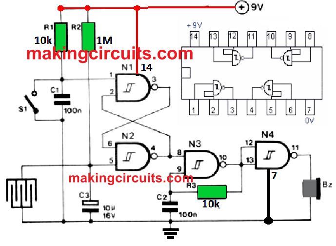
water sensor circuit

The sensors which remain in series with resistor R2 and the two together form a voltage divider which is dependent on humidity.

The voltage divider resets the R-S bi-stable when input 1 of N2 drops down. At that point oscillator N3 is switched on and the buzzer is being energized by the driver N4.

The bi-stable is automatically set when the power goes up via the R1 and C1 series combination.

One can also modify this water sensor circuit as a lie-detector. In that case the sensor is needed to be replaced by two lengths of wire.

This particular wire’s ends are being stripped. The stripped wires are bare and it is then placed in the hands of the person who will be interrogated for lie-detection. If the person lies, his hands will go moist by sweat.

Due to the dampness of his hands the buzzer will make a noise. The sensitivity of the circuit is being calculated by the value of R2.

However, some experiments are still required in this regard. The switch S1 helps to disable the oscillator and the buzzer.

You'll also like:

  • 1.  Automatic Garden Watering Circuit
  • 2.  Garden Soil Moisture Status Indicator Circuit
  • 3.  How to Make a Industrial Tank water fill/drain controller circuit
  • 4.  IC 4017 Automatic Water Level Controller Circuit
  • 5.  Car Tank Water Sensor Circuit without Corrosion
  • 6.  Water Level Controller using a Single SCR

About Admin

Hey friends, Thanks a bunch for stopping by this site! I am an engineer with a Bachelor of Engineering in Electronics and Telecommunication. One of my passions is gathering information from all sorts of electronics books and tutorials. I then take that information and compile it into a language that is super easy to understand. My goal is to make those complex electronics circuit concepts and technical terms much more accessible for all the new and budding electronics engineers out there. I can also design customized circuit diagrams as required by the users.
If you have any questions related to this field, please do not hesitate to drop a comment! I am always here and ready to help you out with any queries you might have. I cannot wait to hear from you!

Reader Interactions

Leave a Reply Cancel reply

Your email address will not be published. Required fields are marked *

Primary Sidebar

Categories

  • 3 Phase (4)
  • 8051 Microcontroller (1)
  • Arduino (11)
  • Audio and Amplifier (102)
  • Automation (8)
  • Battery Chargers (64)
  • Bicycle Projects (4)
  • Car and Motorcycle Projects (39)
  • Datasheets (10)
  • DIY Projects (5)
  • Electrical (15)
  • Free Energy (6)
  • Games Projects (2)
  • High Voltage (14)
  • Hobby Projects (30)
  • Household Circuits (2)
  • IC 555 Circuits (5)
  • Ignition Circuits (2)
  • Indicators (50)
  • Infrared (6)
  • Inverter Circuits (29)
  • Lights and Lamps (97)
  • Medical (8)
  • Meter and Tester Circuits (38)
  • Motor Driver (17)
  • New Circuits (56)
  • Oscillators (30)
  • Pets and Pests (5)
  • Power supply (80)
  • Protection Circuits (25)
  • PWM (9)
  • Remote Control (20)
  • Security and Alarm Circuit (48)
  • Sensors and Detectors (66)
  • Signal Processor (23)
  • Solar Controller Circuits (62)
  • SSR (3)
  • Temperature Controller (20)
  • Timer (25)
  • Transformerless (7)
  • Transmitters (12)
  • Tutorials (45)
  • UPS (2)
  • Voltage Regulators (57)
  • Water Sensor and Controller (29)
  • Home
  • Privacy Policy
  • Contact
  • Disclaimer
  • Copyright

© 2025 · Making Easy Circuits