• Skip to main content
  • Skip to primary sidebar

Making Easy Circuits

Learn and build electronic circuits

You are here: Home / New Circuits / Sound Operated Music Bell

Sound Operated Music Bell

Last Updated on January 10, 2018 by Admin 1 Comment

In this post we learn how to make a simple sound operated music bell circuit which can be installed in homes for enabling the visitors to ring the door bell by knocking on the door.

A doorbell is sine qua non in every household. Most of the standard types need human intervention to operate. But how about a bell that you don’t need to operate, rather it works as a music bell operated by sound? This article will attempt to explain the idea behind building a simple sound operated music bell.
Following is a circuit diagram of the proposed project:

sound activated door bell circuit
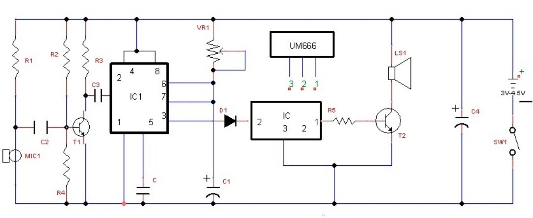
Above shown is the Circuit Diagram of sound operated music bell
Referring to the circuit, the external relay has not been used. The circuit constitutes a timer stage [NE555], melody stage of around SL100 and UM66, and trigger stage of around NE555. The transistor used in this circuit BC548B is in biased state on Class C operation. The sound generating every second impacts on Pin 2 IC timer 555.
With VR1at its max state, approx., 30 seconds is the hold-on time on NE555. However, as per the requirement we need to set the value lower by VR1and the same is done as per the calculation: T = 1.1*VR1*C1
Here it is important to note that the resistance of the preset in the circuit is VR1. IC UM66 has 64 notes of ROM which produces in series and further with the sound of clap. This leads to the trigger of the timer. The output of IC NE555 at Pin 3 is therefore used via IN4001 diode and further to the Pin 2 of IC UM66. As S UM66 starts receiving supply, it generates electrical fluctuation of music at the base of SL100. The music generated is then heard from the attached 4-ohm speaker.

Following are the list of equipment that you need to build this simple and effective solution:
Resistors Capacitors Semiconductors Others
R1 = 10 KΩ C1 = 22 µF/16V IC1 = NE555 MIC1 = 34 LOD condensers microphone
R2 = 470 KΩ C2 = 0.1 µF IC2 = UM66 SW1 = On/Off switch
R3 = 2.2 KΩ C3 = 0.22 µF T1 = BC548B
R4 = 150 KΩ C4 = 220 µF/10V T2 = SL100
R5 = 100 Ω C5 = 0.01 µF D1 = 1N4001
VR1 = 1 MΩ

NOTE: All resistors should be ¼ watt and ± 5% Carbon.

You'll also like:

  • 1.  How to Modify a Bluetooth Headset Device for Personalized Applications
  • 2.  Simplest Transistor Running Light Circuit for Christmas Lighting Decoration
  • 3.  Simple DC Bulb Flasher Circuit
  • 4.  How To Design Simple Power Supply Circuit
  • 5.  0 – 30 V Regulated Power Supply Circuit
  • 6.  Simple Melody Tone Generator Circuit

About Admin

Hey friends, Thanks a bunch for stopping by this site! I am an engineer with a Bachelor of Engineering in Electronics and Telecommunication. One of my passions is gathering information from all sorts of electronics books and tutorials. I then take that information and compile it into a language that is super easy to understand. My goal is to make those complex electronics circuit concepts and technical terms much more accessible for all the new and budding electronics engineers out there. I can also design customized circuit diagrams as required by the users.
If you have any questions related to this field, please do not hesitate to drop a comment! I am always here and ready to help you out with any queries you might have. I cannot wait to hear from you!

Reader Interactions

Comments

  1. Nyongesa says

    June 21, 2022 at 1:01 am

    Good work but can I please see the block diagram of the project and a good explanation on fabrication

    Reply

Leave a Reply Cancel reply

Your email address will not be published. Required fields are marked *

Primary Sidebar

Categories

  • 3 Phase (4)
  • 8051 Microcontroller (1)
  • Arduino (11)
  • Audio and Amplifier (102)
  • Automation (8)
  • Battery Chargers (64)
  • Bicycle Projects (4)
  • Car and Motorcycle Projects (39)
  • Datasheets (10)
  • DIY Projects (5)
  • Electrical (15)
  • Free Energy (6)
  • Games Projects (2)
  • High Voltage (14)
  • Hobby Projects (30)
  • Household Circuits (2)
  • IC 555 Circuits (5)
  • Ignition Circuits (2)
  • Indicators (50)
  • Infrared (6)
  • Inverter Circuits (29)
  • Lights and Lamps (97)
  • Medical (8)
  • Meter and Tester Circuits (38)
  • Motor Driver (17)
  • New Circuits (56)
  • Oscillators (30)
  • Pets and Pests (5)
  • Power supply (80)
  • Protection Circuits (25)
  • PWM (9)
  • Remote Control (20)
  • Security and Alarm Circuit (48)
  • Sensors and Detectors (66)
  • Signal Processor (23)
  • Solar Controller Circuits (62)
  • SSR (3)
  • Temperature Controller (20)
  • Timer (25)
  • Transformerless (7)
  • Transmitters (12)
  • Tutorials (45)
  • UPS (2)
  • Voltage Regulators (57)
  • Water Sensor and Controller (29)
  • Home
  • Privacy Policy
  • Contact
  • Disclaimer
  • Copyright

© 2025 · Making Easy Circuits